
Summary of Contents for omran tahvieh OALC 010
- Page 1 AIR COOLED CHILLERS Air CooledChillers OALC 010 thru OALC 240 10 TR thru 240 TR 35 kW thru 844 kW...
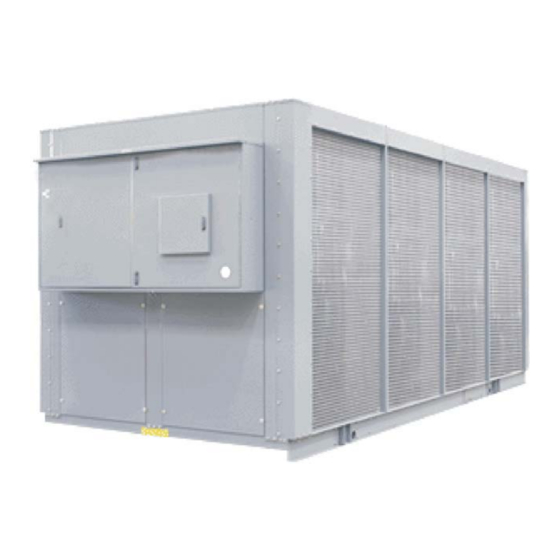
- Page 2 AIR COOLED CHILLERS COMPONENTS CONDENSER COIL CONTROL PANEL USER INTERFACE BOARD MAIN BOARD ACCESS PANEL...
-
Page 3: Table Of Contents
AIR COOLED CHILLERS INDEX Contents Page Model decoding ............................4 Features ..............................4 Standard specifications ......................... 5-7 Standard safety devices, accessories & options ..................8 Physical data ............................9 -10 Selection procedure .......................... 11-12 Ethylene glycol solution capacity correction ................... 13 Performance data .......................... -
Page 4: Model Decoding
AIR COOLED CHILLERS MODEL DECODING 5, 6 & 7 1, 2, 3 & 4 ACCESORIES OPTIONS BASIC NOMINAL COOLING ELECTRICAL SUPPL Y COMPRESSOR TYPE CONDENSER CONTROLS CAPACITY (TONS) ( V-Ph-Hz ) (SERIES) COIL OALC H: SEMI-HERMETIC STANDARD A : STANDARD A : STANDARD A : ALUMINUM H : 208/230-3-60... -
Page 5: Standard Specifications
On multiple compressor units, capacity is controlled by a combination of cylinder unloading and compressor staging. See the following table for the standard and optional capacity control for each unit. % FULL LOAD CAP ACITY CONTROL MODEL NUMBER OPTIONAL OPTIONAL OALC 010 100-50-OFF 100-50-HGBP-OFF OALC 015 100-50-OFF 100-50-HGBP-OFF... - Page 6 AIR COOLED CHILLERS STANDARD SPECIFICATIONS COMPACT DESIGN SHELL AND TUBE WATER COOLERS The DX shell & tube chillers made of low fin copper tubes expanded into a heavy steel tubular sheets. The chiller shell & baffles are constructed of steel and brass respectively. The barrel is insulated with heavy closed cellular foam insulation.
- Page 7 AIR COOLED CHILLERS STANDARD SPECIFICATIONS CONDENSER FANS Condenser fans are constructed with aluminum or steel or PPG or PAG blades on steel hubs with direct driven motors. All fans are statically and dynamically balanced to operate at minimum noise and vibration. Fan blades are designed with appropriate pitch angle which result in maximum airflow through the condenser coil.
-
Page 8: Standard Safety Devices, Accessories & Options
AIR COOLED CHILLERS STANDARD CONTROL & SAFETY DEVICES MICROPROCESSOR CONTROLLER: This controller monitors analog and digital inputs to achieve precise control & safety functions of the unit.( optional ) COMPRESSOR MOTOR INTERNAL OVERLOAD: The internal overload protects the compressor and senses the mo- tor winding temperature in case of overload. -
Page 9: Physical Data
AIR COOLED CHILLERS PHYSICAL DATA MODEL NUMBER OALC 010 OALC 015 OALC 025 OALC 030 OALC 035 OALC 040 OALC 050 OALC 060 OALC 070 COMPRESSOR 800-677-59 (1) 800-677-62 (1) 800-677-68 (1) 800-677-71 (1) PART NUMBER 208/230V-3Ph-60Hz 800-677-44 800-677-50 800-677-62... - Page 10 AIR COOLED CHILLERS PHYSICAL DATA MODEL NUMBER OALC 080 OALC 100 OALC 120 OALC 140 OALC 160 OALC 180 OALC 200 OALC 220 OALC 240 COMPRESSOR PART NUMBER 208/230V-3Ph-60Hz 800-677-74 800-674-42 800-674-48 800-677-71 800-677-74 800-674-42 800-674-42 800-674-48 800-674-48 800-677-34 (1) 800-674-39 (1) 800-674-45 (1) 800-677-31 (3)
-
Page 11: Selection Procedure
AIR COOLED CHILLERS SELECTION PROCEDURE (English units) DESIGN REQUIREMENTS CAPACITY The followingdesign requirementsmust be known to select a packagechiller . ELEV ATION ABOVE CORRECTION SEA LEVEL (FT .) 1. Required cooling capacity in tons FACT OR 2. Leaving chilled water temperature in F (LCWT) 1.00 2000... - Page 12 AIR COOLED CHILLERS SELECTION PROCEDURE (Metric units) DESIGN REQUIREMENTS The followingdesign requirementsmust be known to select a proper packagechiller . CAPACITY ELEVATION ABOVE CORRECTION 1. Required cooling capacity in kilowatt (kW) SEA LEVEL (Meter) FACT OR 2. Leaving chilled water temperature in C (LCWT) 1.00 0.99...
-
Page 13: Ethylene Glycol Solution Capacity Correction
AIR COOLED CHILLERS ETHYLENE GLYCOL SOLUTION CAPACITY CORRECTION (Antifreeze) When operating in areas with temperatures below 32 F (0 C), cooler protection in the form of Ethylene glycol solution (brine solution) is required to protect cooler from low ambient freeze-up. This brine solution must be added to water loop to bring down the freezing point with a difference of 15 F (8 C) below minimum operating ambient temperature. -
Page 14: Performance Data
AIR COOLED CHILLERS PERFORMANCE DATA, 60Hz (English units) - Page 15 AIR COOLED CHILLERS PERFORMANCE DATA, 60Hz (English units)
- Page 16 AIR COOLED CHILLERS PERFORMANCE DATA, 60Hz (Metric units)
- Page 17 AIR COOLED CHILLERS PERFORMANCE DATA, 60Hz (Metric units)
-
Page 18: Electrical Data
AIR COOLED CHILLERS ELECTRICAL DATA... - Page 19 AIR COOLED CHILLERS ELECTRICAL DATA...
-
Page 20: Water Side Pressure Drop
AIR COOLED CHILLERS WATER SIDE PRESSURE DROP 600 700 1000 FLOW RATE - GPM MODEL NUMBER CURVE No. Minimum GPM Maximum GPM 20.7 101.7 OALC 010 20.7 101.7 OALC 015 20.7 101.7 OALC 025 20.7 101.7 OALC 030 20.7 101.7 OALC 035 34.3... -
Page 21: Dimensions
AIR COOLED CHILLERS DIMENSIONS OALC 010 & OALC 015 WATER OUT WATER IN LIFTING HOLE (4) END VIEW FRONT VIEW OALC 025 WATER OUT WATER IN LIFTING HOLE (4) 1400 END VIEW FRONT VIEW OALC 030 & OALC 2203 CONTROL BOX... - Page 22 AIR COOLED CHILLERS DIMENSIONS OALC 040 & OALC 050 2203 CONTROL BOX WATER IN WATER OUT LIFTING HOLE (4) 3/4" MOUNTING 2096 HOLES (TYP.) 2140 FRONT VIEW END VIEW OALC 060 & OALC 070 2203 CONTROL BOX WATER IN WATER OUT LIFTING HOLE (4) 3/4"...
- Page 23 AIR COOLED CHILLERS DIMENSIONS...
- Page 24 AIR COOLED CHILLERS DIMENSIONS...
- Page 25 AIR COOLED CHILLERS DIMENSIONS...
- Page 26 AIR COOLED CHILLERS DIMENSIONS...
- Page 27 AIR COOLED CHILLERS DIMENSIONS...
-
Page 28: Typical Schematic Wiring Diagram
AIR COOLED CHILLERS TYPICAL SCHEMATIC WIRING DIAGRAM LEGEND ANALOG INPUT COMPRESSOR CONNECTION WITH PART WIND START CIRCUIT BREAKER OPTION & CIRCUIT BREAKER COMP COMPRESSOR COMPRESSOR CONTACTOR COMPRESSOR CONTACTOR AUXILIARY CHILLED WATER PUMP INTERLOCK FLOW SWITCH FAN MOTOR FUSE HGBS HOT GAS BYPASS SOLENOID HVTB HIGH VOLTAGE TERMINAL BLOCK INPUT/OUTPUT... -
Page 29: Microprocessor Controller
AIR COOLED CHILLERS TYPICAL MICROPROCESSOR CONTROLLER (OPTIONAL) Sequence of Operation The following describes the sequence of operation for a two compressor reciprocating chiller unit. Operation is similar for a one or four compressor unit. For initial start-up, the following conditions must be met: ·... -
Page 30: Troubleshooting Guide
AIR COOLED CHILLERS Compressorand UnloaderStaging A one compressor unit has 2 stages, two compressor unit has 4 stages and a four compressor unit has 8 stages. The odd numbered stages turn compressors #1 ON or OFF while the even numbered stages de-energized the unloader. The staging of a standard unit is shown in the following chart: Number of Compressors Stage... - Page 31 AIR COOLED CHILLERS TROUBLESHOOTING GUIDE 6) No LED H1 blinking light on NG3 Board a) Check power supply cable an connection. b) Check if the power supply voltage is into the specified limits: 24Vac +/- 10%. c) Check for fuse F1, replace with 1AT/250V if blown. 7) No display of leds on User Interface Board a) Check serial cable integrity.
-
Page 32: Application Data
AIR COOLED CHILLERS APPLICATION DATA UNIT PLACEMENT: Prior to unit installation, please check the following points. Strength, level of the base or founda- tion. Please refer unit installation clearance dimensional drawings for proper unit installation. CONDENSER AIRFLOW: Obstructed flow of condenser air will effect the unit capacity and operating efficiency. It is essential to install the units where sufficient airflow available to eliminate condenser discharge air recirculation. - Page 33 AIR COOLED CHILLERS APPLICATION DATA AIR CONDITIONING APPLICATIONS PROCESS APPLICATIONS UNIT MODEL GALLONS LITERS GALLONS LITERS OALC 010 OALC 015 OALC 025 OALC 030 OALC 035 OALC 040 1000 OALC 050 OALC 060 1310 1503 OALC 070 1780 OALC 080...
-
Page 34: Rigging Instructions
CAUTION All panels should be in place when rigging. Care must be taken to avoid damage to the coils during handling. Insert packing material between coils & slings as necessary. MODELS: OALC 010 - OALC 070 LIFT LIFT SPREADER BAR... -
Page 35: Installation Clearance
AIR COOLED CHILLERS INSTALLATION CLEARANCE WALL 3048 FIGURE - 1 2438 2438 WALL FIGURE - 2 SINGLE UNIT IN PIT 2438 2438 2438 WALL FIGURE - 3 DOUBLE UNITS IN PIT 2438 FIGURE - 4 CORNER WALL... -
Page 36: Parts List
AIR COOLED CHILLERS PARTS LIST MODEL NUMBER OALC 010H OALC 010F OALC 010M OALC 010L OALC 015H OALC 015F OALC 015M OALC 015L OALC 025H OALC 025F OALC 025M OALC 025L 800-097-42(2) COMPRESSOR STARTER 800-097-42 800-097-36 800-097-36 800-097-36 800-097-45 800-097-36 800-097-39 800-097-39 800-097-42... - Page 37 AIR COOLED CHILLERS PARTS LIST MODEL NUMBER OALC 050H OALC 050F OALC 050M OALC 050L OALC 060H OALC 060F OALC 060M OALC 060L OALC 070H OALC 070F OALC 070M OALC 070L 800-097-42(4) 800-097-45(4) 800-097-48(4) 800-097-42(4) 800-097-42(4) COMPRESSOR STARTER 800-097-42(2) 800-097-45(2) 800-097-45(2) 800-097-45(2) 800-097-48(2)
- Page 38 AIR COOLED CHILLERS PARTS LIST MODEL NUMBER OALC 140H OALC 140F OALC 140M OALC 140L OALC 160H OALC 160F OALC 160M OALC 160L OALC 180H OALC 180F OALC 180M OALC 180L 800-097-51(2) 800-097-48(2) COMPRESSOR STARTER 800-097-57(4) 800-097-48(2) 800-097-48(4) 800-097-48(8) 800-097-48(4) 800-097-42(8) 800-097-45(8) 800-097-51(8)
Need help?
Do you have a question about the OALC 010 and is the answer not in the manual?
Questions and answers