Table of Contents
Advertisement
Quick Links
Advertisement
Table of Contents

Summary of Contents for Alutherm heating A 170
- Page 1 Alutherm A 170-300 Installation, user and service manual/instructions for user...
- Page 2 Alutherm A 170 - 300 Heating INSTRUCTIONS FOR USER If you have questions concerning the use of your boiler or heating system, please ask your installer. It is in your own interest and that of the installer that you are aware of how to operate your boiler and heating system safely and efficiently.
-
Page 3: Table Of Contents
Alutherm A 170 - 300 Heating CONTENT 1 DESCRIPTION BOILER 2 TECHNICAL DATA Component matrix 3 DIMENSIONS 4 OPERATION General Central Heating (CH) 4.2.1 On-off room thermostat 4.2.2 Optional 0-10V 4.2.3 Outside Temperature Control OTC (optional) 4.2.4 Optional digital communication 4.2.5... - Page 4 Alutherm A 170 - 300 Heating 7 Commissioning 7.1 Gas category 7.2 Adjustment % CO2 and check input 8 ERRORS 8.1 General 8.2 DHW errors 8.3 CH-errors 8.4 Errors (hard and soft lockouts) 9 ANNUAL INSPECTION MAINTENANCE 9.1 Service-maintenance table 9.2 Tubing and fixation...
-
Page 5: Description Boiler
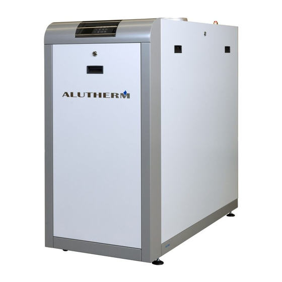
Alutherm A 170 - 300 Heating DESCRIPTION BOILER 1 Terminal strip 2 Boiler controller (Maxsys) 3 Gas valve 4 Flow 5 Exhaust 6 Automatic air vent 7 Fan 8 Venturi 9 Return 10 Return NTC 11 Fill and drain valve... -
Page 6: Technical Data
Alutherm A 170 - 300 Heating TECHNICAL DATA TECHNICAL DATA ALUTHERM A 170-300 A 170 A 210 A 260 A 300 Central heating Nominal input max load (Hi) Nominal input min load (Hi) 33,6 50,4 58,8 Nominal ouput max load 80-60 °C... -
Page 7: Component Matrix
Alutherm A 170 - 300 Heating COMPONENT MATRIX COMPONENT MATRIX PART A 170 A 210 A 260 A 300 Boiler control Honeywell Maxsys S4966V2052 S4966V2052 S4966V2052 S4966V2052 Display (user interface) DSP 49G2193 DSP 49G2193 DSP 49G2193 DSP 49G2193 Fan MVL 230 VAC... -
Page 8: Dimensions
Alutherm A 170 - 300 Heating DIMENSIONS Type A 170 - A 210 - A 260 - A 300 The appliance is not to be used by children or persons with reduced physical, sensory or mental capabilities, or lack of experience and knowledge. Children, even if being supervised, must not play with the appliance. -
Page 9: Operation
Alutherm A 170 - 300 Heating In the case of failure or malfunction of the appliance, do not attempt to repair it yourself. Please contact your installer. Repairs must only be carried out by qualified technicians. Failure to comply with these requirements can compromise the safety of the appliance. -
Page 10: Outside Temperature Control Otc (Optional)
Alutherm A 170 - 300 Heating 4.2.3 Outside Temperature Control OTC (optional) The boiler may use an outdoor sensor to provide weather compensation (OTC). To activate weather compensation, connect an outdoor sensor to numbers 5 and 6 on the terminal strip C2. Pin numbers 1 and 2 have to be bridged by a wire. Alternatively, those pin numbers (1 and 2) can be used for connecting room thermostat on/off. -
Page 11: Slow Start
Alutherm A 170 - 300 Heating 4.2.5 Slow start The boiler uses a “slow start” procedure to prevent the boiler from supplying excessive power in low load situations. After “zero check” APS and closure APS with pre purge ignition starts. Following a stabilization period, the boiler modulates down to low capacity and maintains this capacity for 1 minute. -
Page 12: Domestic Hot Water (Dhw)
Alutherm A 170 - 300 Heating Domestic Hot Water (DHW) 4.3.1 External storage tank with thermostat (electric 3-way valve)* As standard the DHW configuration is factory pre-set for an external storage tank + tank thermostat. For hydraulic connection of an external storage tank to the boiler via an electric 3-way valve one should either use:... -
Page 13: Boiler Control
Alutherm A 170 - 300 Heating BOILER CONTROL Control Panel The control panel has 12 buttons and a display as shown in the figure below. Push buttons on control panel Description of push button use ALUTERM A 170 - 300... -
Page 14: User Menu
Alutherm A 170 - 300 Heating User menu By pressing the “menu-button” the display will show the text as given in the figure below. By pressing the button marked “3” in the figure above the user menu is accessed. Pressing the button marked “5”... - Page 15 Alutherm A 170 - 300 Heating ALUTERM A 170 - 300 Installation, user and service manual instructions for user ALUTHERM Boilers 15...
- Page 16 Alutherm A 170 - 300 Heating ALUTERM A 170 - 300 Installation, user and service manual instructions for user ALUTHERM Boilers 16...
-
Page 17: Installer (Technician) Menu
Alutherm A 170 - 300 Heating Installer (technician) menu If the button marked “4” (page 21) is pressed the screen as given in the figure below will appear. Once the menu is accessed by entering the code the following options will be shown 1. - Page 18 Alutherm A 170 - 300 Heating ALUTERM A 170 - 300 Installation, user and service manual instructions for user ALUTHERM Boilers 18...
- Page 19 Alutherm A 170 - 300 Heating ALUTERM A 170 - 300 Installation, user and service manual instructions for user ALUTHERM Boilers 19...
- Page 20 Alutherm A 170 - 300 Heating ALUTERM A 170 - 300 Installation, user and service manual instructions for user ALUTHERM Boilers 20...
- Page 21 Alutherm A 170 - 300 Heating ALUTERM A 170 - 300 Installation, user and service manual instructions for user ALUTHERM Boilers 21...
- Page 22 Alutherm A 170 - 300 Heating ALUTERM A 170 - 300 Installation, user and service manual instructions for user ALUTHERM Boilers 22...
-
Page 23: Manual Chimney Sweep Mode
Alutherm A 170 - 300 Heating Manual Chimney sweep mode For routine maintenance and/or service purposes a CH request can be generated to force the burner to a specific load from minimum to nominal (0-100%). This is only possible if no error condition is present. The chimney sweep function can be started from the user menu and will be active for 15 minutes.While active it is possible to navigate through other menus to check the boiler status and functionality. - Page 24 Alutherm A 170 - 300 Heating ALUTERM A 170 - 300 Installation, user and service manual instructions for user ALUTHERM Boilers 24...
- Page 25 Alutherm A 170 - 300 Heating ALUTERM A 170 - 300 Installation, user and service manual instructions for user ALUTHERM Boilers 25...
-
Page 26: Installation
Alutherm A 170 - 300 Heating INSTALLATION Installing the boiler The installation must be done in accordance with all local and national codes, regulations and standards, and in accordance with the directives of all relevant authorities. 1. The boiler must only be installed in an area where it is allowed to install it. -
Page 27: Water Connection
The boiler does not have a built in CH-pump. Therefore, a CH-pump must be mounted separately . Select a pump that matches the hydraulic resistance of the boiler and the installation. Hydraulic pressure drop Alutherm series A 170 - A 210 - A 260 - A 300 A 170... -
Page 28: Water-Treatment
Alutherm A 170 - 300 Heating 6.3.3 Water-treatment Before filling up the installation (old and new), the installation should be rinsed thoroughly with clean water from the tap.There are some rinsing/cleaning products listed below and it is recommended that these are used. -
Page 29: Water Connection General
Alutherm A 170 - 300 Heating 6.3.4 Water connection general 1. Water connections for flow and return are size 2” 2. The installation must have a pressure relief valve (with a capacity higher than the boiler output), mounted in the flow as close as possible (within 50 cm to the threaded connection) to the heat exchanger and an expansion vessel. -
Page 30: C53
Alutherm A 170 - 300 Heating 6.5.4 Roof and wall terminals (see page 43) and expanders and/or condensate trap/collector must be obtained by M&G. For pressure drop calculation of appliance type C53 use the table for pressure drop per component and the table for total pressure drop calculation. -
Page 31: Pressure Drop Calculations
Alutherm A 170 - 300 Heating Table below gives the equivalent of pipe length in meter of bend 90°, 45° Equivalent of pipe length in meters Bend Pipe diameter ø200 mm Ø180 mm ø150 mm Ø110 mm Bend 90° 5,75 Bend 45°... - Page 32 Alutherm A 170 - 300 Heating Boiler type Component A 170 A 210 A 260 A 300 Pressure drop [Pa] Flue gas Flue gas Flue gas Flue gas [Pa] [Pa] [Pa] [Pa] [Pa] [Pa] [Pa] [Pa] Pipe length 1 m Ø...
- Page 33 Alutherm A 170 - 300 Heating Table for total pressure drop calculation Number Flue Number Air delta pressure delta pressure Total pressure Total pressure Total pressure Ø150mm component component Air drop Fluegas drop Air in drop Flue gas Ø250mm Fluegas...
- Page 34 Alutherm A 170 - 300 Heating APPLIANCE TYPE FLUEGAS SUPPLY AIR APPLIANCE TYPE APPLIANCE TYPE APPLIANCE TYPE FLUEGAS SUPPLY AIR FLUEGAS FLUEGAS FLUEGAS SUPPLY AIR SUPPLY AIR SUPPLY AIR OUTLET INLET OUTLET INLET OUTLET OUTLET OUTLET INLET INLET INLET APPLIANCE TYPE...
- Page 35 Alutherm A 170 - 300 Heating COMPONENTS OEM ART. NO M&G PP Ø 200 mm ELBOW PP 200 90° EPDM 41.007.04.11 ELBOW PP 200 45° EPDM 41.007.04.12 EXTENSION PP 200x500 41.007.04.01 EXTENSION PP 200x1000 41.007.04.02 EXTENSION PP 200x1900 41.007.04.04 ROOFTERM PP 200 7021 B23-C53 41.007.04.39...
-
Page 36: Dop
Alutherm A 170 - 300 Heating 6.5.8 All the prescribed articles (flue and air) must be installed in accordance with the following DOP’s: For aluminium: 0.1 (Dn 60-250) (rigid, single) (flue) T200 P1 W V1 L10/11/13 150 030 For PP: 0.8 (Dn 200), (rigid, single) (flue) T120 P1 W1/2 030 LI E U... -
Page 37: Brackets, Mounting
Alutherm A 170 - 300 Heating 6.6.2 Brackets, mounting Air inlet • The first bracket should be mounted 0.5 mtr away from the boiler • Horizontal and non-vertical pipes should be bracketed equally divided with a maximum distance of 1 mtr between the brackets •... -
Page 38: Electrical Connection
Alutherm A 170 - 300 Heating Electrical connection 1. The electrical installation should be in accordance with national and local codes and regulations. 2. As standard the boiler is configured for 230 VAC / 50 Hz 3. The terminal strip is accessible by opening the front cover behind which the control is mounted. - Page 39 Alutherm A 170 - 300 Heating 6.7.1 Wiring diagram Burner control Display Connector 230V Connector low voltage CH-P Central heating pump DHW-P Domestic hot water pump PWM-P Modulating pump Appliance pump max 0,8A Heat exchanger NTC1 Flow temperature sensor NTC2...
-
Page 40: 6.6.1 Wiring Diagram
Alutherm A 170 - 300 Heating 6.6.1 WIRING DIAGRAM 6.7.1 Wiring diagram ALUTERM A 170 - 300 Installation, user and service manual instructions for user ALUTHERM Boilers 40 Installation, Usage and Maintenance Instructions... -
Page 41: Ntc Resistance Table
Alutherm A 170 - 300 Heating 6.7.2 NTC Resistance Table NTC resistance table Temperature [°C] Resistance [kΩ] 98.200 75.900 58.800 45.900 36.100 28.600 22.800 18.300 14.700 12.000 9.800 8.050 6.650 5.520 4.610 3.860 3.250 2.340 1.940 1.410 1.470 1.260 1.100... -
Page 42: 6.8 Pneumatic Connections
INSTALLATION MANUAL DEJATECH FLOORFLEX Alutherm A 170 - 300 Heating INSTALLATION MANUAL DEJATECH FLOORFLEX 6.8 Pneumatic connections 6.8 Pneumatic connections A pneumatic diagram for the Floorflex 168 kW (5 sections) and the Floorflex 294 kW (8 Pneumatic connections sections) is given in the figure below. -
Page 43: Commissioning
Alutherm A 170 - 300 Heating COMMISSIONING 1. Fill and bleed the system. Fill the boiler until a pressure between 1.5 and 2 bar is achieved. The maximum working pressure is 6 bar. The boiler (not the installation!) is automatically bled by a built-in automatic air vent. -
Page 44: Gas Category
Alutherm A 170 - 300 Heating Gas category The types of gas and supply pressures vary per country. In the table below the gas category and supply pressure are listed per country. Countries Countries Category Pressure [mbar] As the responsible manufacturer of my products, I’m aware... -
Page 45: Adjustment % Co2 And Check Input
Alutherm A 170 - 300 Heating Adjustment % CO2 and check input The boiler is equipped with an automatic gas/air regulator. This means that the amount of gas is regulated depending on the amount of air. The % CO2 needs to be adjusted according to the table below;... -
Page 46: Errors
Alutherm A 170 - 300 Heating ERRORS General If there is no data visible on the display, the fuse (5,0 AT) in the control panel near the main switch should be checked (as well as the position of the on/off switch) and should if required be replaced (after the cause for break down has been determined and rectified). -
Page 47: Dhw Errors
Alutherm A 170 - 300 Heating F1: T3.15A 250 V F2: T3.15A 250 V If you are not sure that there is any heat demand, you can force the boiler to start as described in 5.5. At heat demand, the boiler control will perform a zero-check of the air pressure switch before starting the fan. Following this, the fan will start and wait for the air pressure switch to close. - Page 48 Alutherm A 170 - 300 Heating Errors (hard and soft lockouts) Errors are indicated by a text and an E-code on the bottom line on the display. The error message can be displayed by pressing the ”information” button Following an error with a hard lockout, the boiler will not fire again until a manual reset is performed (eg max temp limit).
-
Page 49: Errors (Hard And Soft Lockouts)
Alutherm A 170 - 300 Heating Errors (hard and soft lockouts) Hard Description Cause of the fault checking and fi nding a solution for the fault Lockout Code Failed ignition The burner failed to light after 3 ignition 1. Check gas supply to boiler. - Page 50 Alutherm A 170 - 300 Heating Errors (hard and soft lockouts) Hard Description Cause of the fault checking and fi nding a solution for the fault Lockout Code E 31 Supply Sensor Open An open circuit has been detected in the 1.
- Page 51 Alutherm A 170 - 300 Heating Errors (hard and soft lockouts) Hard Description Cause of the fault checking and fi nding a solution for the fault Lockout Code VPS Check time out *) E 89 Incorrect Setting A parameter setting is outside the 1.
-
Page 52: Annual Inspection Maintenance
Alutherm A 170 - 300 Heating ANNUAL INSPECTION MAINTENANCE Maintenance must only be done by a qualified installer or technician. The appliance must be inspected once every year according to table 9.1. Maintenance and inspection must be done once every two years according to table 9.1... - Page 53 Alutherm A 170 - 300 Heating Procedure putting back in place inspection covers on the left-hand side of the heat-exchanger First slide the lower bar over the M8 studs Then mount the lower nuts loose (2-3 rotations) Then put for each opening and inspection cover foreseen with a seal...
-
Page 54: Service-Maintenance Table
Alutherm A 170 - 300 Heating Service-maintenance table When commissioning/inspecting the boiler CO2, CO, T flow, T return, ΔP air pressure switch and Psyphon pressure switch must be measured and the measured values must be written down in the table below. - Page 55 Alutherm A 170 - 300 Heating Service-maintenance table Date Gasflow [m3/h] Tflow Treturn P air P syphon or load [kW] [ppm] [°C] [°C] pressure pressure switch [mbar switch [mbar] Installed Installed + 1 year inspection Installed + 2 year maintenance...
-
Page 56: Tubing And Fixation
Alutherm A 170 - 300 Heating Tubing and fixation During the inspection and maintenance also all the tubing and its fixations as shown in the pneumatic diagram in chapter 6.8 must be checked. Check for leakage and correct fixation. In case of doubt replace tubing and or fixation. -
Page 57: Torque Table
Alutherm A 170 - 300 Heating Torque table Torque table Concerning part Torque in Nm Inspection cover sump Burner hood on heat-exchanger Venturi on fan Fan on burner hood Air-inlet on fan Gas valve on fan Electrode ignition Electrode ionisation... - Page 58 EC Conformity Declaration 0063 0063CQ3790 Alutherm Heating B.V., Craenakker 3a, NL 5951 CC Belfeld, The Netherlands, hereby declares that the condensing central heating boilers, type Alutherm A 170-300 Conform to and comply with the essential requirements of the following European standards and directives.
- Page 59 Alutherm Heating B.V. Craenakker 3a 5951 CC Belfeld The Netherlands Telephone +31 (0)77 303 19 76 E-mail info@aluthermheating.nl Website www.aluthermheating.nl...
Need help?
Do you have a question about the A 170 and is the answer not in the manual?
Questions and answers