Advertisement
Quick Links
PRODUCT NAME :
DIMENSIONS
ITEM NO.
Note:
-Please make sure all parts and proper quantities are included.
-Do not use power tools. We recommend you hand-tighten screws.
Use care not to overtighten.
tools needed
(not included)
1. Check for damaged or missing parts . Call 1-800-696-8446 to order missing supplies.
2. Use a soft surface or the carton as a working surface to prevent damage during assembly.
3. It is recommended to have 2 adults on hand for assembly.
4. Gather all tools prior to assembly.
5. WARNING! When included, anti-tipping hardware MUST be installed for your safety.
QUESTIONS? Call 1-800-696-8446, or email cs@ptsamerica.com
ASSEMBLY INSTRUCTIONS
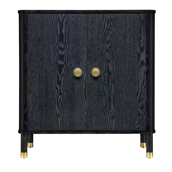
BUREN 2-DOOR CABINET
: 31.5"W x 14.96"D x 33.7"H
: 7241BK581A1W23 (BLACK)
7241BR581A1W23 (BROWN)
PAGE 1 OF 11
c 2021. PTS America, lnc. All rights reserved.
Advertisement

Subscribe to Our Youtube Channel
Related Manuals for Sango 7241BK581A1W23


Summary of Contents for Sango 7241BK581A1W23
- Page 1 BUREN 2-DOOR CABINET PRODUCT NAME : : 31.5”W x 14.96”D x 33.7”H DIMENSIONS ITEM NO. : 7241BK581A1W23 (BLACK) 7241BR581A1W23 (BROWN) Note: -Please make sure all parts and proper quantities are included. -Do not use power tools. We recommend you hand-tighten screws.
-
Page 2: Parts List
PAGE 2 OF 11 PARTS LIST : Top panel Left side panel Right side panel Bottom panel Left door Right door Shelf Back panel Side post 2pcs QUESTIONS? Call 1-800-696-8446, or email cs@ptsamerica.com c 2021. PTS America, lnc. All rights reserved. - Page 3 PAGE 3 OF 11 HARDWARE : 8pcs Cam Bolt Cam Lock 8pcs 16pcs Wooden Dowel Ø 8x25mm 4pcs Leg Ø 38x140mm 4pcs Screw for Bottom 2pcs Handle 2pcs Screw for Handle Magnet 2pcs Screw for Magnet 2pcs Metal Plate 2pcs Screw for Metal Plate 4pcs Shelf Pin...
- Page 4 PAGE 4 OF 11 How to use cam lock system tools needed (not included) QUESTIONS? Call 1-800-696-8446, or email cs@ptsamerica.com c 2021. PTS America, lnc. All rights reserved.
- Page 5 PAGE 5 OF 11 STEP-1 1 x8 STEP-2 8 x1 9 x2 3 x16 QUESTIONS? Call 1-800-696-8446, or email cs@ptsamerica.com c 2021. PTS America, lnc. All rights reserved.
- Page 6 PAGE 6 OF 11 STEP-2 STEP-3 QUESTIONS? Call 1-800-696-8446, or email cs@ptsamerica.com c 2021. PTS America, lnc. All rights reserved.
- Page 7 PAGE 7 OF 11 STEP-4 5 x4 STEP-5 4 x4 QUESTIONS? Call 1-800-696-8446, or email cs@ptsamerica.com c 2021. PTS America, lnc. All rights reserved.
- Page 8 PAGE 8 OF 11 STEP-6 STEP-7 QUESTIONS? Call 1-800-696-8446, or email cs@ptsamerica.com c 2021. PTS America, lnc. All rights reserved.
- Page 9 PAGE 9 OF 11 STEP-8 STEP-9 Lock plastic wedge bracket on 6 corners of the back panel. QUESTIONS? Call 1-800-696-8446, or email cs@ptsamerica.com c 2021. PTS America, lnc. All rights reserved.
- Page 10 PAGE 10 OF 11 STEP-10 STEP-12 First, align the pin pre-installed in Door Panel (E & F) and insert to the pre-drilled hole on Bottom Panel (D). Then insert the pin on another side of Door Panel (E or F) to Top Panel (A).
- Page 11 PAGE 11 OF 11 STEP-11 STEP-12 STEP-11 Note: adjust levelers on an uneven floor. STEP-12 INSTALL THE TIP-OVER CABLE 16 x2 17 x1 18 x1 19 x1 20 x1 Screw into wall stud if available. Use anchor on hollow wall. WARNING! Team Lifting Required.
Need help?
Do you have a question about the 7241BK581A1W23 and is the answer not in the manual?
Questions and answers