Table of Contents
Advertisement
Quick Links
Advertisement
Table of Contents

Summary of Contents for Sunwa CARRY-UP CU406
- Page 1 CARRY-UP OPERATION MANUAL Doc. No. SUNWA LTD. ME - 08 - 1 ...
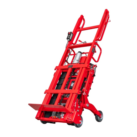
- Page 2 INTRODUCTION Thank you for purchasing Heavy Duty Carrier Series, SUNWA CARRY-UP. This manual describes proper operating procedure, inspection and maintenance. Before running the machine, be sure to read this manual thoroughly. Please keep this manual on easy place to take it.
-
Page 3: Table Of Contents
TABLE OF CONTENTS 1. ESSENTIALS OF SAFE OPERATION 2. CONFIGURATION AND SPECIFICATIONS PRODUCT CONFIGURATION 2-1 ・ ・ ・ ・ ・ ・ ・ ・ ・ ・ ・ ・ ・ ・ ・ ・ ・ ・ ・ ・ ・ ・ ・ ・ ・ ・ ・ ・ ・ ・ ・ ・ ・ ・ ・ ・ ・ ・ ・ ・ ・ SPECIFICATIONS 2-2 ... -
Page 4: Essentials Of Safe Operation
ESSENTIALS OF SAFE OPERATION Before using CARRY-UP ● CARRY-UP cannot be used on spiral staircases, curved staircases, staircase angle exceeding 35 degrees, Stairs with larger pitch or Stairs with rough edges. 35 degrees or larger < Spiral staircase > < Staircase with curve > <... - Page 5 2 Handling of Battery ● Battery is a sealed type. It is unnecessary to refill it with water. Never dismantle Battery. ● Never position Battery near a flame or short-circuit Battery. ● If Battery is cracked and its electrolytic solution contacts skin or clothes, immediately rinse contaminated area with plenty of water.
-
Page 6: Configuration And Specifications
CONFIGURATION AND SPECIFICATIONS PRODUCT CONFIGURATION 2-1 CARRY-UP consists of the following assemblies. • Cargo Frame • Drive Unit • Assist Wheel • Cargo tie (5m) 1 set Standard • Battery Pack accessories • Charger (24V) 1 unit •... -
Page 7: Name Of Each Unit
NAME OF EACH UNIT ●Sliding Fork Type ●Fixed Fork Type (Model SF) Handle Handle Straight Handle Switch Box Operation Switch Switch Box Operation Switch Brake Lever Assist Wheel Lock Lever Assist Wheel Lock Lever Relay Box Frame Unit Brake Lever Frame Unit Drive Unit Drive Unit... -
Page 8: Description Of Each Unit 5~10
DESCRIPTION OF EACH UNIT KEY SWITCH 4-1 Key Switch, positioned atop relay box turns on/off the power supply. Relay Box When it is turned clockwise, the power will be ON Key Switch and when turned counter-clockwise, the power will be OFF. NOTE : When CARRY-UP is not to be used (to be stored, to be charged, to be transported), turn off Key Switch, remove Key and keep it in... -
Page 9: Wheel Brake
WHEEL BRAKE 4-3 When Brake Lever is set to its ON position, Main Wheels will be prevented from running. To release the brake, set the brake position to OFF. Brake Lever Before stopping CARRY-UP on level ground or rais- ing/lowering its frame, be sure to apply the brake to 「ON」 ... -
Page 10: Assist Wheel
ASSIST WHEEL 4-4 Before CARRY-UP climbs the stairs, be sure to fully retract its Assist Wheels. ● When Assist Wheels are to be used: ① Pull Assist Wheel Lock Lever in the arrowed di- rection shown in the figure at right. Lock Pin will be released and Assist Wheels will extend from the Assist Wheel Lock Lever... - Page 11 SLIDE FORK UNIT(Model SF) 4-5 Slide Fork Unit is used for stair ascent/descent and during ground transfer for cargo balance adjustment. Set Select Switch on Switch Box to TOE PLATE and control Slide Fork Unit via its switch. When Slide Fork Unit reaches its highest or lowest positions, the upper or lower Limit Switches will ac- tivate, and Slide Fork Unit will automatically stop.
-
Page 12: Battery Pack Removal And Reinstallation
BATTERY PACK REMOVAL AND REINSTALLATION 4-6 Loosen Battery Pack's Plug Screw and disconnect ① Plug from its receptacle. Pay attention not to pull the cord to disconnect Plug. Receptacle Screw Charger's Plug The lower receptacle is exclusive for battery charging. Loosen Butterfly Head Bolt that secures Battery ② ... -
Page 13: Battery Gauge Inspection
BATTERY GAUGE INSPECTION 4-7 ■ BATTERY GAUGE Relay Box • Check that the right end lamp of Battery Gauge is illuminated. When charge level decreases, illumination will shift to the left. If Battery Gauge is not illuminated at the right end, it means Battery is not fully charged or battery capacity is reduced due to its deterioration. -
Page 14: Battery Charge System 11~15
BATTERY CHARGE SYSTEM BATTERY 5-1 A Sealed Lead Battery is used in CARRY-UP. It is a maintenance-free and non water requiring Battery. Whenever Battery is handled, be sure to follow the cautions shown below. NOTE : Immediately after Battery is used, Battery must be charged using Battery Charger of CARRY-UP. -
Page 15: Charging Procedure
CHARGING PROCEDURE 5-3 [ Front Panel ] [ Rear Panel ] Cooling Fan Charger Power Output Fuse Voltage Range Power Switch Power LED(Red) Charging LED(Yellow ⇒ Green) Power Plug Charger's Plug ① Connect Battery Charger's Plug to Receptacle of Battery Pack. Receptacle Battery Pack Charger's Plug... -
Page 16: Voltage Range Selection
③ Turn on Charger's Power Switch. (Set it to Yellow LED [ Rear Panel ] (Start of charging process) When Red and Yellow LEDs illuminate, the charging process will start. Green LED Power Switch Red LED When the charging process advances and Green ④... -
Page 17: Malfunction, Inspection, Resolution Procedure
MALFUNCTION, INSPECTION, RESOLUTION PROCEDURE 5-6 TROUBLE CAUSE COUNTERMEASURE Insufficient insertion of Power Plug Check outlet and securely connect into outlet. Power Plug. No power is supplied. Check power and other relevant parts. Power Cord is broken. Arrange its repair or replacement. -
Page 18: Battery Replacement
BATTERY REPLACEMENT 5-7 Unscrew the screws mounting Battery Case and ① Battery Cover. Battery Case Screw Screw Battery Disconnect cables from Battery Terminals, remove ② exhausted Batteries, and install new ones. (−) (+) ③ Connect cables to Battery Terminals as shown in ... -
Page 19: Pre-Use Inspection 16~17
PRE-USE INSPECTION Before using the machine, be sure to carry out the daily inspection. The daily inspection will prevent trouble. It is essential before handling CARRY-UP. SWITCH INSPECTION Switch Box Upper Limit Switch Relay Box Key Switch Emergency Stop Switch UP/DOWN Lower Limit Switch Switch... - Page 20 WHEEL BRAKE INSPECTION 「ON」 「OFF」 Brake Lever 「ON」 「OFF」 Adjust the Adjustment Screw screw length. Adjustment Screw Wheel Brake • Check that Main Wheel Brake for ground transfer functions normally. BATTERY GAUGE INSPECTION RUBBER CRAWLER INSPECTION Rubber Crawler Slip Mark The right end LED illuminates •...
-
Page 21: Operation 18~31
OPERATION CARGO SECURING PROCEDURE 7-1 Load the cargo on Fork and tighten it securely with the attached Cargo Tie. Fixed Fork Model [ ] Cargo Tie shall be tightened at slight upper position Cargo Tie from the middle position of cargo. Cargo Tie must be hooked to Pipes for Hook that are positioned at Both sides of Frame. - Page 22 ● Cargo Tie securing procedure ① Set Cargo Tie to the hook on the machine, and tighten Cargo Tie firmly while pressing Cargo to the machine. After Cargo is in place, raise and tighten the buckle. Before starting operation, be sure to check that ② ...
- Page 23 GROUND TRANSFER 7-2 Apply the brake for ground transfer. ① 「ON」 Before starting ground transfer, be sure to extend ② Brake Lever Assist Wheels to maintain safety. Pull the handle carefully to Assist Wheel's side to tilt the machine as below. Handle Unit Assist Handle...
- Page 24 After balancing the machine, release Main Wheel ③ brake and manually transfer CARRY-UP with cargo Brake Lever by its Main Wheels and Assist Wheels. 「OFF」 Ground Transfer Using Assist Wheels for ground transfer adds the ④ Swiveled stability of four wheel support. However, when CARRY-UP is needed to turn, use only Main Wheels carefully after making machine stand up- right.
-
Page 25: Ascending Stairs
ASCENDING STAIRS 7-3 Position CARRY-UP at the stairs ① When the machine reaches the front of the bottom stair, apply brakes to Main Wheels, raise Frame and Assist Wheel retract Assist Wheels. Lock Lever Brake Lever Approach the stairs with the machine and set it at a ② ... - Page 26 ③ Tilt slowly until Rubber Crawler contact the sec- ond stair. Model SF: Model SF [ ] Set Select Switch to TOE PLATE and lower Slide Fork Unit. The machine should easily and safely level up to align with the stairs. Pay attention that both Rubber Crawler approach the first stair at right angle.
- Page 27 (3) Improper weight balance: Lay the machine on the stairs with Main Wheels a little aloft. If the top of the machine (handle side) is floated, the center of gravity should be in the bottom side. Danger will result. Reload Cargo with its center of gravity on the upper side of the machine.
- Page 28 (5) Temporary stoppage If the operator releases Operation Switch, Electro Magnetic Brake will function and the machine will immediately stop. Rubber Crawler lugs catch the stair noses prevent- ing the machine from sliding down. If cargo balance and the machine stopping position are unstable, a dangerous situation may occur.
- Page 29 ③ When the machine reaches the landing, retract As- sist Wheels and transfer and turne the machine on its Main Wheels. If a landing is too small to operate the machine, pay attention to maintaining enough space to raise and turne the machine.
-
Page 30: Descending Stairs
DESCENDING STAIRS 7-4 (1) Start descending When the machine reaches the edge of the top stair, ① retract Assist Wheels. NOTE : The operator must stand upward of the ma- chine during descent. Check that Select Switch is set to DRIVE and then ② ... - Page 31 ③ When the bottom end of Rubber Crawlers reach the second stair, stop the machine, lift up Handle 「ON」 carefully to make machine position at a right angle Brake Lever to the stair with keeping the balance. (2) Proper weight balance To check the weight balance lay the machine on the stairs with Main Wheels a little aloft.
- Page 32 (3) Improper weight balance If the top of the machine (handle side) is aloft, the center of gravity is on the bottom side. Danger will result. Reload Cargo with its center of gravity on the higher side of the machine. If it is difficult to shift the center of gravity to the higher side, main- tain pressure on the handle toward the stairs by ap- plying the operator's weight.
- Page 33 (5) Stop descent When the machine has nearly reached the bottom ① floor, stop the machine. Apply Main Wheel Brake by raising Brake Lever. ② Brake Lever When Main Wheels contact the ground, raise the 「ON」 machine carefully. Model SF: If Slide Fork Unit is highly posi- tioned, be sure to lower it.
- Page 34 ③ Release Main Wheel Brake and manually transfer Brake Lever the machine. 「OFF」 Model SF: [ Model SF ] When Main Wheels contact the ground, lower Slide Fork Unit to shift the center of gravity to promote easier raising of the machine. The operator must be trained for stair ascent/descent op- erations and turning operation on landings.
-
Page 35: Rubber Crawlers Adjustment And Replacement 32~36
RUBBER CRAWLERS ADJUSTMENT AND REPLACEMENT Since Jan. 2005, Rubber Crawler specifications for CU-406 to CU606SF Series were revised in keeping with model improvements. 8-1 ADJUSTMENT (1) Tension adjustment Raise the machine upright, then loosen Tension ① Shaft Mount Nut. Tension Shaft Mount Nut ② ... - Page 36 (2) Rubber Crawler alignment correction Set Select Switch to DRIVE and press DOWN or UP to power Rubber Crawlers. Check that Rubber Crawler keeps running on cen- ter of Sprocket Wheel. If the angle of Sprocket Wheel is incorrect, Rubber Crawler deviates gradu- Drive ally from the center of Sprocket Wheel.
- Page 37 RUBBER CRAWLER PITCH ERROR CORRECTION PROCEDURE 8-2 Rubber Crawler pitch error will prevent smooth stair ascent/descent and may cause Rubber Crawler derail- ment. Loosen Tension Shaft Mount Nut. Turn Adjustment ① Bolt counter-clockwise in order to loosen Rubber Crawler. Tension Shaft Mount Nut Adjustment Bolt ② ...
-
Page 38: Rubber Crawler Replacement Procedure
RUBBER CRAWLER REPLACEMENT 8-3 Disconnect the winch and Limit Switches wire har- ① ness connector from Switch Box and remove the winch and Limit Switches wire harness from the chassis. Limit Switch Connector Winch Motor Connector Remove Mount Bolts and nuts that connect the ② ... - Page 39 ③ Loosen Drive Unit's Tension Shaft Mount Nut. Turn Adjustment Bolt counter-clockwise to loosen Rubber Crawler. Remove Rubber Crawler. Tension Shaft Mount Nut Adjustment Bolt Mount New Rubber Crawler with the reverse procedure of its removal. Align the two Rubber Crawlers' lugs with ④ ...
-
Page 40: Daily Maintenance And Care
DAILY MAINTENANCE AND CARE BATTERY 9-1 ● When CARRY-UP is not to be used or its Battery Pack is to be charged, turn off Key Switch and remove Key. If Key Switch is kept in the ON position, Battery will quickly discharge and it may not have capacity to run CARRY-UP the following day. -
Page 41: Inspection And Maintenance
INSPECTION AND MAINTENANCE Daily maintenance keeps CARRY-UP in good condition. Lack of daily inspection will greatly reduce the life of CARRY-UP. To prevent possible trouble and to extend CARRY-UP's life, undertake daily inspections. CHECK ITEM CHECK PROCEDURE COUNTERMEASURE Key Switch (Relay Box) Check its functioning. - Page 42 ● If any trouble or malfunction has arisen which is not described in the preceding table, contact the sales agency. An improper countermeasure may cause danger. ● For details on periodical inspections, consult the sales agency where you purchased CARRY-UP.
- Page 43 SUNWA LTD. 571 Negishi. Sayama. Saitama 350-1325. Japan Phone : +81-4-2954-6611 Fax : +81-4-2954-6617 URL : http://www.sunwa-jp.co.jp 2007. 4...
Need help?
Do you have a question about the CARRY-UP CU406 and is the answer not in the manual?
Questions and answers