Table of Contents
Troubleshooting

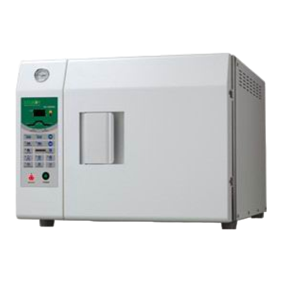
Summary of Contents for Sturdy SA-300MA
- Page 1 “ ” “ ” SA-300MA / SA-300MA-R Instruction Manual Please read manual carefully before using and keep it well.
-
Page 3: Table Of Contents
6.13.1 Sterilization for Implements ................34 6.13.2 Sterilization for Wrap ..................36 6.13.3 Placement for sterilization box ................36 6.13.4 Glassware ......................37 7. Recorder (SA-300MA-R) ......................38 7.1 Intended use ......................... 38 7.2 Recording contents ....................... 38 7.2.1 Description of Detail Content ................39... - Page 4 7.2.2 Description of Summary Contents ..............40 7.3 Storage medium ......................42 7.4 Recorder panel ......................43 7.5 Function description of the recorder ................43 7.5.1 General ....................... 44 7.5.1.1 Stand-by mode ....................44 7.5.1.2 Recording mode ....................44 7.5.1.3 Adjusting mode ....................45 7.5.2 Set up .........................
-
Page 5: Important Safety Instructions
1. Important Safety Instructions In order to clearly indicate the extent of the harm, loss or damage which may result from falling to heed these precautions and the degree of their urgency, the precaution have been classified into the three categories of Danger, Warning and Caution. Danger:This indicates an imminently hazardous situation arising from the mishandling or mis-operation of the unit which, if not avoided, might cause the death or serious injury of the operator or other persons. - Page 6 Warning: DO NOT place alcohol or other flammable items in the sterilizer. An explosion could occur, causing personal injury. Gasoline Alcohol Chemical…… Figure 2 Warning: A separate (dedicated) circuit is recommended for the sterilizer. The sterilizer should not be connected to an electrical circuit with other appliances or equipment.
- Page 7 Warning: Children are not allowed to use or play with the unit. Figure 5 Warning: Do not put your fingers into the gap on the hinged side of the door. Figure 6 Warning: Always check the pressure gauge before opening the door. DO NOT attempt to open the door if the pressure is not at zero (0).
- Page 8 Warning: In an emergency, or before carrying out any maintenance, always disconnect the power cord from the outlet. Figure 8 Warning: Use sterilization indicator test strips to check that sterilization has been successful. Figure 9 Warning: If the ALARM indicator light illuminates, the machine is over-pressure or overheated.
- Page 9 Warning: Use only distilled water. Normal tap water contains minerals, especially chlorides, which have corrosive effects on stainless steel. Failure to use distilled water will invalidate the warranty. Pure Water City Water Groundwater …… Figure 11 Caution: Do not put objects on the power plug or power cord. Figure 12 Caution: The outer casing and metal surfaces of the sterilizer will be hot during operation, please do not touch it.
- Page 10 Caution: Do not place objects on top of the water intake cap. Figure 14 Caution: Always check the water level in the reservoir before running a sterilization cycle. If the LOW WATER indicator light illuminates, add distilled water. If the water is sufficient, but the LOW WATER indicator light is still illuminating, refer to Troubleshooting.
- Page 11 Caution: The ADD WATER indicator light will illuminate during the sterilization cycle. This is part of normal operation and no action on the part of the user is required. Figure 17 Caution: Steam and hot water will be present when opening the door after a sterilizer cycle. Avoid contact.
- Page 12 Caution: Do not tip over the unit or allow it to fall on the power plug. Figure 20 Caution: It will require at least two (2) or more people to carry the sterilizer to avoid dropping it off by mistake. Figure 21 Caution: Always allow a minimum of 20 min.
- Page 13 Caution: Please unplug the power cord and drain off water from the reservoir if the sterilizer will not be used regularly. Figure 23 Caution: Always keep the sterilizer clean. Figure 24...
-
Page 14: Explanation Of Safety Symbols And Notes
2. Explanation of Safety Symbols and Notes Caution, consult instruction manual for use Protective earth (ground) Alternating Current Attention! Hot surface Disposal of Electrical & Electronic Equipment (WEEE): This product should be handed over to an applicable collection point for the recycling of electrical and electronic equipment. -
Page 15: Unpacking
3. Unpacking Caution: It will require at least two (2) or more people to carry the sterilizer to avoid dropping it off by mistake. Wall Base Figure 25 Cut the banding Lift off the top cover of the carton Remove the wall and the foam packaging inserts Carefully lift the sterilizer from the packaging base Check all accessories are present as follows (accessories are packed inside the sterilizer chamber):... -
Page 16: Installation
4. Installation 4.1 Environment This equipment has been designed for use in accordance with the International EMC (Electromagnetic Compatibility) Standards. In view of different environments, please follow the instructions given below to eliminate interference, if necessary. Move the equipment or rotate its direction; Enlarge the space between the equipment and other machines;... - Page 17 Open the water reservoir cap; pour distilled water into the water reservoir as Figure 26. Water Reservoir Cap Water Level Figure 26 Caution: Please fill Distilled Water Only into the unit. Please do not fill water over the yellow water level mark as Figure 27 and Figure 32. Yellow Water level Mark Water Level Figure 27...
- Page 18 Install the heater cover to the chamber as Figure 28 (standard accessory) Ensure the rounded edge is towards the back and the vertical front edge of the cover locates securely into the corresponding slots in the lower part of the chamber opening. Heater Cover Chamber Water Stopper...
- Page 19 D. Install the tray frame as Figure 30 (optional accessory). Caution: The frame should be installed as Figure 30 below. The indention of the frame will pass the bushing in the chamber. Tray Frame Indention Figure 30 Install the tray as Figure 31. (optional accessory) Tray Frame Tray Heater Cover...
- Page 20 G. Ensure the Power Switch is in OFF “O” position, and then plug the power cord into a separate (dedicated) mains socket. Warning: A separate (dedicated) socket is required for the sterilizer. Make sure the socket is earthed and can offer the capacity of 16 A / 230V AC. Warning: The plug is one of the measures of emergency cutoff;...
-
Page 21: Introduction
5. Introduction 5.1 Intended Use This product is a tabletop high pressure steam sterilizer which is designed and developed for the sterilization of wrapped and unwrapped items. It can also perform sterilization of liquid which is not for medical purpose*. (*Liquid, Flash program and recorder are optional by order.) 5.2 Description of the Sterilizer 5.2.1 External View... -
Page 22: Internal Configuration
Exhaust Hose / Maintenance Water Level Cover Indicator Power Cord Figure 34 5.2.2 Internal Configuration Temperature Sensor Heater Pressure Sensor Water Level Sensor Over temperature controller Water Stopper Figure 35... -
Page 23: Control Panel (Re-Dry Program)
Indicates over-temperature or Display “REC” with recorder type (optional). over-pressure in the chamber. Process Status Indicator SA-300MA Individual LED light to Low Water Indicator Light indicate the current status Indicates the water level is of the sterilization below the minimum level or the program. -
Page 24: Control Panel ( Liquid Program ) / ( Optional By Order Request )
Indicates over-temperature or Display “REC” with recorder type (optional). over-pressure in the chamber. Process Status Indicator SA-300MA Individual LED light to Low Water Indicator Light indicate the current status Indicates the water level is of the sterilization below the minimum level or the program. -
Page 25: Operation
6. Operation 6.1 Operation Overview 6.1.1 Re-Dry Program Put the sterilization items and close door Standard Sterilization Program Select Sterilization Temp.121°C or 134°C Select Re-Dry Button Select Sterilization Item Select Dry Time 0/15/30/35/40 min. Press “START” Button Vacuum, Add Water and Heat Re-Dry (10 min.) Repeat Vacuum and Heat steps for 4 times, and then... -
Page 26: Liquid Program
6.1.2 Liquid Program Put the sterilization items and close door Standard Sterilization Program Select Select Sterilization Temp.121°C or 134°C Liquid Program Select Sterilization Item Button Select Dry/No Dry 0/15/30/35/40 min. Press “START” Button Vacuum, Add Water and Heat Liquid Program Heat to Sterilization Repeat Vacuum and Heat steps for 4 times, and then Heat to Selected Sterilization Temperature. -
Page 27: Pump Test / Bd Test / Prion
6.1.3 PUMP test / BD test / PRION Put the sterilization items and close door B.D. test, PRION Pump Test Press “START” Button Vacuum, Add Water and Heat Vacuum (10 min.) Repeat Vacuum and Heat steps for 4 times, and then Heat to Selected Sterilization Temperature. -
Page 28: Prepare Sterilization
6.2 Prepare Sterilization Follow “4. Installation” to finish installation first. Follow “4.2 Install the sterilizer” to make sure the water inside reservoir is sufficient. C. Check the Pressure Gauge is reading ZERO, and then open the door by turning the door knob 90°... -
Page 29: Standard Sterilization Program
6.3 Standard Sterilization Program Before start Sterilization program please refer to “6.2 Prepare Sterilization” section. How to set the Standard Sterilization program 121°C or 134°C 120°C 103°C 0 bar (Room Temp.)°C (kgf/cm Vacuum Figure 40 C. Press “STERI TEMP” to select 121°C or 134°C D. -
Page 30: Re-Dry Program (Exclusive Either To Liquid Or Flash Functions)
On completion, the buzzer will sound same time the display will flash. The program has finished when the buzzer STOPS and the COMPLETE indicator light is illuminated on the Process Status Indicator. Warning: If the COMPLETE indicator light was not lit, the cycle has failed and should be run again. -
Page 31: Liquid Program (Optional, Exclusive Either To Re-Dry Or Flash Function)
6.5 Liquid Program (optional, exclusive either to Re-Dry or Flash function) Before start Sterilization program please refer to “6.2 Prepare Sterilization” section. How to set the Liquid program 121°C 0 bar (Room Temp.)℃ (kgf/cm Figure 43 Caution: After the sterilization step finished, the unit will take to exhaust spontaneously. - Page 32 On completion, the buzzer will sound same time the display will flash. The program has finished when the buzzer STOPS and the COMPLETE indicator light is illuminated on the Process Status Indicator. Warning: If the COMPLETE indicator light was not lit, the cycle has failed and should be run again.
-
Page 33: Prion Program
6.7 PRION Program Before start Sterilization program please refer to “6.2 Prepare Sterilization” section. How to set the PRION program 134°C 120°C 103 °C 0 bar (Room Temp.)°C (kgf/cm Vacuum Figure 45 C. Press to start “PRION Program”. The corresponding sterilization time will be: Sterilization Time 18 min. -
Page 34: Test Program
Open the door and take out the sterilized items. Warning: Check the Pressure Gauge is reading ZERO before opening the door. Warning: Beware of steam when opening door after a sterilization cycle. Warning: Be careful when removing the sterilized items as the metal surfaces might still be hot. - Page 35 selected program. The current progress of the sterilization cycle is indicated by the illuminated LED on the Process Status Indicator. (Figure 48) Note: The DRY step won’t be performed. Figure 48 On completion, the buzzer will sound same time the display will flash. The program has finished when the buzzer STOPS and the COMPLETE indicator light is illuminated on the Process Status Indicator.
-
Page 36: Pump Test Program
6.9 PUMP TEST Program Before start Sterilization program please refer to “6.2 Prepare Sterilization” section. How to set the PUMP TEST program 0 bar (kgf/cm Vacuum Figure 49 C. Press to start “PUMP TEST Program”. The corresponding sterilization time will be: Sterilization Time Sterilization Temperature Dry Time... -
Page 37: Vacuum Release
Warning: Check the Pressure Gauge is reading ZERO before opening the door. 6.10 Vacuum Release Press the Vacuum/Pressure Release Button to release the chamber pressure. The message “OP” will be displayed to notify operation. Please check the Pressure Gauge is reading ZERO before opening the door 6.11 Reset / Stop Press the RESET/STOP Button... -
Page 38: Sterilization For Implements
Warning: To sterilize absorbent cotton or woolen, please wrap it with sterilizing pouch to avoid piping clog. 6.13.1 Sterilization for Implements Place implements on the tray evenly according to Figure 51. Do not pile up nor overlap each implement. Sterilization Indicator Figure 51 Warning: If implements are packed with sterilizing pouches, please make sure not to pile... - Page 39 Figure 54 Figure 55...
-
Page 40: Sterilization For Wrap
Warning: If implements are packed with sterilizing pouches and placed inside a sterilization box, make sure to display items as Figure 56. Figure 56 6.13.2 Sterilization for Wrap Warning: To sterilize absorbent cotton or woolen, please wrap it with a thin towel, covering cloth, linen, or sterilizing pouch to avoid piping clog according to Figure 57. -
Page 41: Glassware
Make sure to close the cover of sterilization box properly. Figure 58 Warning: Please follow above Figure 58 and place wrap vertically inside the sterilization box. 6.13.4 Glassware Use only heat-proof glass. Verify that the beaker is only filled 2/3 full and the lid is on loosely to allow for expansion. Items should not be allowed to touch the walls of the Chamber as the hot metal can damage the item. -
Page 42: Recorder (Sa-300Ma-R)
7. Recorder (SA-300MA-R) 7.1 Intended use This paperless Recorder records the sterilization temperature, theoretical steam pressure and real time information during each cycle as an optional method of printer. It records the specified information onto an USB flash drive, in the Excel csv (Comma Separated Values) format which compatible with Microsoft®... -
Page 43: Description Of Detail Content
7.2.1 Description of Detail Content Printer output Description Model number MODEL:SA-300MA-R Software version installed in this autoclave Version:V0.99 Series number SN:161005204-001 Program selected Program: 134 Unwrapped Sterilization temperature Ster. Temp:134 ºC Sterilization duration Ster. Time: 4 m Dry duration Dry Time: 15 m Date and Time of sterilization Date:2020/03/13... -
Page 44: Description Of Summary Contents
Program complete Message of ending recording Signature:___________ Signature office 7.2.2 Description of Summary Contents Printer output Description Model number MODEL:SA-300MA-R Software version installed in this autoclave Version:V0.99 Series number SN:161005204-001 Program selected Program: 134 Unwrapped Sterilization temperature Ster. Temp:134 ºC Sterilization duration Ster. - Page 45 040:20 136.6 2.14 every 1 minutes after 043:22 98.2 0.08 “S00”; and also the last 058:31 111.3 0.07 sterilization time 059:32 111.2 0.08 exhaust of water and steam dry time-started dry time-finished end of recording The maximum and minimum temperature Ster.
-
Page 46: Storage Medium
7.3 Storage medium Use only recommended storage medium by the manufacturer such as USB (2.0) flash drive. You should format your storage medium prior insert into the Recorder for the first time. You can operate on the files in this card in PC via a card reader. Data will be stored under the root directory only. -
Page 47: Recorder Panel
7.4 Recorder panel ▲Increase button 1) to move cursor backward LCD: 2) to advance digits 1)Display date and time 2)Display chamber temperature 3)Recording status SET button: ▼ Decrease button 1)to set the parameter 1) to move cursor 2)to confirm adjustment forward 2) to decrease digits USB port... -
Page 48: General
7.5.1 General There are 3 types of operation modes for the recorder, they are stand-by mode, recording mode, and adjusting mode. 7.5.1.1 Stand-by mode The date and time will be displayed after turn on the main power, and low battery symbol will flash for charging and/or low battery as shown in Figure 62. -
Page 49: Adjusting Mode
Please Wait ! Data transfer 2019- Apr-24 Completed 13:30:30 Data transfer… Figure 64 Note 1: If none of the USB flash drive being detected before completing a sterilization cycle, 2 warming messages “E105: No USB memory” followed by a buzzer alarm are presented. -
Page 50: Set Up
7.5.2 Set up 7.5.2.1 Set up date and time Press “SET” button for adjusting the parameters of the recorder while in the stand-by mode. Press increase (▲) or decrease (▼) until “1. Date / Time” displayed as shown in Figure 66. 1. -
Page 51: Remove Usb
The sequence is in the order of Temperature - Pressure each time you press the “Set” button. After entering the unit, press “Set” button returns to the Set manual, and then to choose “8. EXIT” press “Set” button again returns to the stand-by mode as shown in Figure 67. 7.5.2.3 Remove USB Caution: The data may be damaged if not follow this operation to detach the USB flash drive properly. -
Page 52: Download
7.5.2.4 Download Warning: The recorder can operate without a USB flash drive, but the data stored in the recorder will be overwritten by the next sterilization data if the recorder memory is full. Manufacturers strongly recommend that you use a USB flash drive as a storage medium and always back up the USB flash drive to a secure area. -
Page 53: Cycle
5. Printer Figure 75 Press the Setup button to select the printer contents, then press the (▲) and/or (▼) buttons to select as shown in Figure 76. Printer: ON Figure 76 Press “SET” button returns to the Back to previous page. 7.5.2.6 SN: Press the "SET"... -
Page 54: Message And Troubleshooting (For Recorder)
7.6 Message and troubleshooting (for recorder) Symptom Solution No display - Turn on the main switch. - Plug the power cable. - Check if bad connection. - Contact local distributor for service E101: Temp. Sensor fail - Contact local distributor for service E103: Pressure sensor - Contact local distributor for service fail... -
Page 55: Test Instructions
8. Test Instructions 8.1 Biological performance of sterilizers It is commonly used as a challenge organism for sterilization validation studies and periodic check of sterilization cycles. The biological indicator contains spores of the organism on filter paper inside a vial. After sterilizing, the cap is closed, an ampoule of growth medium inside of the vial is crushed and the whole vial is incubated. -
Page 56: Air Removal (Bowie-Dick Type Test Pack)
8.2 Air removal (Bowie-Dick type test pack) A commercially available Bowie-Dick type test pack that is of a size appropriate to the chamber being tested. The indicator is a heat sensitive sheet that is placed in the middle of a packet made up of various layers of paper and foam rubber. - Page 57 4. After processing, wear heat-resistant glover to remove the Cube from the sterilizer and allow to cool. Warning: The metal clamp is hot at this stage of test. 5. Unlock the swing-bar and remove the indicator sheet from the center of the Cube. 6.
-
Page 58: Helix Test
8.3 Helix test The Helix test represents a hollow A-type load, i.e. the load with the most critical characteristics. Carry out the test as follows (Example of TST LOADCHEK STEAM): Warning: TST LOADCHEK STEAM is trademark of ALBERT BROWNE LTD., 1. - Page 59 Warning: The HELIX Test kit will be very hot! 6. Open the capsule and remove the test strip. 7. Please ask your dealer of HELIX test. 8. The result is as follows: Incorrect result: Figure 83 Incorrect result: Figure 84 correct result: Figure 85...
-
Page 60: Maintenance Instructions
9. Maintenance Instructions Warning: Failure to follow the Maintenance Instructions will adversely affect performance and lifespan of the sterilizer, and may invalidate the warranty. Warning: Before conducting maintenance, please turn off the sterilizer and disconnect from the power supply. Check the sterilizer has cooled down to room temperature. Warning: Make sure that pressure gauge is reading ZERO before opening the door. - Page 61 Clean the filter. Use a wrench to unscrew the filter nut counterclockwise as Figure 86 and Figure 87. Caution: Place a towel underneath the filter tap to avoid leakage. Counterclockwise Filter Nut Towel Figure 86 Take out the filter following the direction of the arrow.
-
Page 62: Monthly
9.3 Monthly Use the non-corrosive cleaner and stiff bristled brush or sponge to clean the water level sensor at the rear of the chamber as Figure 89. Caution: Clean the dirt off from the sides of the sensor is more important than the tip. Use a damp cloth to wipe the surface after cleaning. -
Page 63: Annually
9.4 Annually Caution: An annual maintenance service by a trained engineer is necessary. Contact your distributor for details. The following maintenance instructions are for your reference only. Calibrate the temperature during sterilization process. (Use biological indicators to test the validity of sterilization) Check if there’s any leakage of the piping. -
Page 64: Troubleshooting
10. Troubleshooting 10.1 Symptoms Problem Possible Cause Solution The main cable is Plug in the sterilizer and turn on the socket unplugged or the switch. socket switch is off. Power Forget to turn on the indicator isn’t Press the Power switch to ON ”I” position. switch. -
Page 65: List Of Error Codes (For Autoclave)
10.2 List of Error Codes (for autoclave) ERROR Description CODE K-type sensor in chamber is out of connection (Emergency light illuminates) The door is not closed completely (Door light illuminates) Sterilization temperature over than 137°C (Emergency light illuminates) The water tank is in LOW WATER condition (LOW-WATER light illuminates) Water in the chamber is not enough in first 5 min. -
Page 66: Specifications
11. Specifications Model SA-300MA SA-300MA-R Chamber Capacity (L) Maximum Instrument Length (mm) Maximum Load (unpouched) (g) 9000 Maximum Load (pouched) (g) 1600 External Dimensions (mm) 900(D) x 620(W) x 489 (H) Chamber Size (mm) 300 Diameter x 570 Depth Gross Weight (kg) -
Page 67: Warranty
Or the products were altered or repaired by anyone other than qualified service personnel. The liability of Sturdy Industrial Co.‚ Ltd. is limited to repair of replacement and under no circumstances shall “STURDY” be liable for any collateral consequential damages or loss. This guarantee specifically excludes the expendables and consumable. - Page 68 Name Sturdy Autoclave Sterilizer Model SA-300MA / SA-300MA-R Sturdy Industrial Co. Ltd. Manufacturer 168, Sec. 1, Zhongxing Rd., Wugu District, Address New Taipei City, 24872, Taiwan APEX MEDICAL S.L. EC Representative Elcano 9, 6 ª planta 48008 Bilbao. Vizcaya SPAIN...
Need help?
Do you have a question about the SA-300MA and is the answer not in the manual?
Questions and answers