
Summary of Contents for Rotary Gate Systems SL-1000
- Page 1 SL – 1000 SLIDE GATE OPERATOR INSTALLATION MANUAL M A DE IN U.S.A . ROTARY GATE SYSTEMS, INC. ALL RIGHTS RESERVED 2008 REV. 3.0 1-877-331-4RGS (4747)
- Page 2 INTRODUCTION The Rotary Gate Systems SL-1000 slide gate operator has been designed to be the most reliable and easiest to install product in its field. The straight forward, compact design ensures that this will be the operator of choice for installer, service technicians and customers alike.
-
Page 3: Table Of Contents
Table of contents Pre-Installation Information …………………………………..4 Before you begin Always check the gate’s action Gate operator classifications Approved obstruction detection device Safety Information and Warnings ……………………………..4 Regulatory warnings Wiring specifications ……………………………………………5 AC power wiring DC control and accessory wiring Earth Ground ................5 Safety Information ………………………………………………..6... -
Page 4: Pre-Installation Information
Pre-installation Information Safety Information and Warnings Before you begin… THE FOLLOWING FORMATS USED FOR Before unpacking, inspect the carton for exterior damage. If SAFETY NOTES IN THESE INSTRUCTIONS. you find damage, advise the delivery carrier of a potential claim. Inspect your package carefully. Claims for shortages WARNING will be honored for only 30 days from the date of shipment. -
Page 5: Wiring Specifications
Wiring Specifications Earth Ground Refer to the following steps for details on power and Install a ground rod and connect it to the operator’s control box accessory wiring for the operator. in every gate operator installation. A good earth ground is necessary to allow the controller’s built-in surge and lightning protection circuitry to work effectively. -
Page 6: Safety Information
Safety Information Gate system designers, sellers, installers, technicians, and users should familiarize themselves with the proper layout designs required to ensure the safe operation of the gates and any accessories associated with them. Any gate system design must include safety devices of sufficient quantity and placement to protect the customer, the general public and technicians working on the system from potential harm. -
Page 7: Access Conrol Devices
Access Control Devices The SL-1000 is compatible with any type of access control device which provides a dry contact relay for activation. SEPARATE PEDESTRIAN ACCESS GATE MUST BE PROVIDED. GATE MUST BE DESIGNED OR SCREENED SUCH THAT NO OPENING MORE THAN 2 1/4"... -
Page 8: Limit Switch Profile
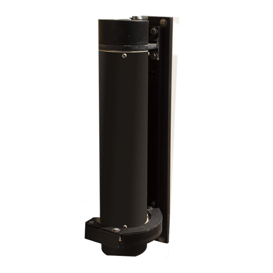
Mounting Operator The SL-1000 mounts directly to one of the gate support posts, if using a cantilever gate, or to an auxiliary mounting post, if no gate support post is available. 1. Decide on a location for the operator; front post, rear post, separate auxiliary post. -
Page 9: 2-Remote Mounting
Option 2: Remote Mounting If mounting the SL-1000 control box remotely from the gate, run wires from the control box for the operator motor, limit switches, photo beams, loops and opening accessories. Power and low voltage wiring should always be installed in separate conduits. -
Page 10: Manual Release
MANUAL RELEASE This gate operator is equipped with a manual release device which requires no tools. To open the gate manually: 1. Turn power switch inside control box OFF before proceeding! 2. To disengage operator and move gate manually, lift keylock cover on top cap, insert key and turn clockwise. -
Page 11: Connecting The Operator
CONNECTING THE OPERATOR After the operator and control box are mounted, connect the operator wires to the APeX control panel. A flex conduit fitting is provided on the bottom for the operator and an additional fitting is included in the accessory bag included with each operator. Use standard non-metallic flex conduit (not provided) to go from the operator to the control box or to a junction box (not provided) which can be mounted on the support post below the operator. -
Page 12: Field Wiring Description
FIELD WIRING LAYOUT THE FOLLOWING TERMINALS ARE LABELED FOR FIELD CONNECTION: BATTERY (WIRES): Connect to (2) 12v5ah batteries found in accessory box. Connect red to positive (+) side of one battery, black to negative (-) terminal on other battery, and connect jumper between remaining terminals on batteries to provide 24 vdc battery backup and motor power. -
Page 13: Troubleshooting
Preventative Maintenance Troubleshooting Contacting Technical Support Always disconnect power from operator before For technical questions regarding ROTARY GATE SYSTEMS servicing. Keep clear of gate during operation. gate operators, please contact the Technical Support Department at 1-877-331-4747. General RGS gate operators are designed for many years of trouble-... - Page 14 SL – 1000 SLIDE GATE OPERATOR PROGRAMMING MANUAL...
- Page 15 Controller Features WHIP ANTENNA ANTENNA CONNECTOR OPERATION AND POWER PROGRAMMING OPERATION INDICATORS INDICATORS BUTTONS DISPLAY PROGRAMMING SOLAR BUTTONS PANEL TERMINALS INPUT POWER MOTOR TERMINALS BOARD COVER ACCESSORY POWER BATTERY TERMINALS CONTROLLER TERMINALS RESET BUTTON PLUG-IN TERMINALS LOOP PRIMARY/ DETECTOR SECONDARY CONNECTORS COMM LINK TERMINALS...
- Page 16 Indicator Descriptions INDICATOR DEFINITION INDICATION WHEN LIT INDICATION WHEN LIT DURING NORMAL OPERATION DURING PROGRAMMING OPERATION PROGRAMMING 24 VOLT INPUT LOW VOLTAGE AC POWER IS PRESENT POWER 24 VOLT DC LOW VOLTAGE DC POWER IS PRESENT ACCY POWER OPEN SIGNAL PRESENT FROM THE INTERNAL OPEN RECEIVER OR AN EXTERNAL DEVICE CONNECTED TO THE OPEN INPUT TERMINAL...
- Page 17 Terminal Descriptions TERMINAL GROUP FUNCTION AC N FACTORY CONNECTED TO 24 VAC FROM 24 VDC FROM 24 VOLT INPUT CONTINUOUS DUTY DC SUPPLY. DC - ACCESSORY POWER PROVIDES 24 VOLT DC POWER FOR ACCESSORIES. (.5A MAX) DC + RESET RESET BUTTON FACTORY CONNECTED TO THE CONTROLLER’S RESET BUTTON.
- Page 18 Operator Accessory Connections 3-BUTTON STATION TELEPHONE ENTRY PHOTOEYE FOR REVERSE KEYPAD PHOTOEYE FOR CLOSE OBSTRUCTION (B1) KEYSWITCH SOLENOID LOCK FIRE ACCESS SWITCH EXTERNAL POWER PHOTOEYE FOR OPEN OBSTRUCTION (B1) SINGLE-CHANNEL RADIO RECEIVER MAGLOCK GATE EDGE SENSOR FOR REVERSE (B2) WARNING STROBE OR AUDIBLE SOUNDER WIRELESS GATE EDGE SENSOR TRANSMITTER Figure 11.
- Page 19 Basic Controller Programming Programming Overview PROGRAM The Controller can be programmed with various options for the operator. INDICATOR The programming fields are defined as “functions” that have “options”. DOWN To make setup easier for the installer, the Controller’s programming is divided into two groups: basic and advanced.
- Page 20 Basic Controller Programming (Cont.) Run Alarm and Pre-start Alarm FUNCTION OPTIONS RUN ALARM OFF The factory default is Run Alarm on and a 3-second Pre-start Alarm. The "RP" PRE-START ALARM OFF operator’s beeper will sound 3 seconds before the operator starts. The options are: RUN ALARM ON PRESS UP OR...
- Page 21 Obstruction detection type – b1, b2 FUNCTION OPTIONS B1 is a non-contact sensor such as a photo eye. B2 is a contact sensor "OT" FOR NON-CONTACT SENSOR such as an edge. This setting affects behavior in the closed direction obstruction detection. If a B2 detector is used, the operator will only allow FOR CONTACT SENSOR an input 2 times to continue automatic closing until a closed limit switch is successfully made.
- Page 22 Advanced Controller Programming Entering Advanced Programming Mode FUNCTION OPTIONS ADVANCED PROGRAMMING FUNCTIONS To access and program the Advanced Programming functions, for each "AD" WILL NOT BE DISPLAYED programming session, Advanced Programming must be enabled. ADVANCED PROGRAMMING OPTIONS After exiting programming, the Advanced Programming functions WILL BE DISPLAYED will be available on the programming display during the next programming session unless the operator has run 50 or more...
- Page 23 Advanced Controller Programming (Cont.) Stagger Delay Time (Rarely used in slide gate installations) FUNCTION OPTIONS This function is used in dual gate installations only. The factory STAGGER TIMER DISABLED "ST" default sets the Stagger Time to 0 seconds (OFF). The Stagger Time sets the delay for the Stagger Mode.
- Page 24 Advanced Controller Programming (Cont.) Shadow Loop Open Prevention FUNCTION OPTIONS STANDARD OPERATION If the shadow loop is triggered, it always prevents the gate from closing if "SP" SHADOW LOOP INHIBITS CLOSING ONLY the Auto Close Timer activates or a CLOSE command is given while the gate is at the full open position.
- Page 25 Advanced Controller Programming (Cont.) Soft Start/Stop Duration FUNCTION OPTIONS This function causes the operator to start and stop the DC motor SOFT START DISABLED "SS" slowly reducing gate wear and tear (at the full open or closed positions only). The factory default sets the Soft Start/Stop Duration to SET SOFT START DURATION TIME 3 seconds.
- Page 26 Advanced Controller Programming (Cont.) Mid-travel Stop Position FUNCTION OPTIONS MID-TRAVEL STOP DISABLED The Controller can be programmed so the gate will stop at a mid-travel "MT" (GATE RUNS FULL TRAVEL) point instead of fully opening. This can be useful in installations where a large gate, that takes a long time to open and close fully, only needs to SET LENGTH OF OPENING TIME FROM 1 TO 99 SECONDS...
- Page 27 Advanced Controller Programming (Cont.) FUNCTION OPTIONS Radio Enable "RA" INTERNAL RADIO RECEIVER DISABLED The Controller contains a built-in MegaCode radio receiver to allow ® activation from up to 40 access control transmitters and two Model MGT (gate edge) transmitters. The factory default enables the internal radio INTERNAL RADIO RECEIVER ENABLED receiver.
- Page 28 STORED IN MEMORY. DO NOT USE THIS FEATURE UNLESS INSTRUCTED TO NOTE: THIS FUNCTION WILL NOT ERASE TRANSMITTERS, CURRENT SENSE VALUES, DO SO BY ROTARY GATE SYSTEMS TECH SUPPORT. OR MOTOR TYPE. RESET TO FACTORY DEFAULTS Minimum settings for programming . If an “illegal” setting is chosen, the operator will flash EN 15 upon exiting programming and self-adjust settings to the minimums below .
- Page 29 Dual Gate Installations Two operators can be used in dual gate installations. The operators DUAL GATE OPERATOR #1 communicate with each other through the 3-wire COMM LINK terminals. COMM LINK WIRING SHIELD When one operator activates, the COMM LINK connection signals the other operator to activate.
- Page 30 Gate Operation Reverse Input If the reverse input is triggered while the gate is closing, the Open Button gate will reverse to the full open position . If the Auto Close Opens the gate . If the Controller is programmed to stop Timer is set, when the reverse input is cleared, the gate will opening the gate at mid-travel, a constant press of the OPEN close when the Auto Close Timer expires .
- Page 31 Error Indications CONTROLLER ERROR CAUSES AND INDICATIONS During abnormal operation, the Controller’s displays and ERROR CAUSE ERROR INDICATION HOW TO CLEAR beeper will indicate the error condition that has occurred . TWO SAFETY REVERSALS (ON En 00, CONTINUOUS ALARM SINGLE GATE OR ON EITHER PRESS STOP BUTTON BEEPER, GATE DISABLED DUAL GATE)
- Page 32 Gate Operator Installation Checklist INSTALLER CUSTOMER ❑ ❑ The gate has been checked to make sure it is level and moves freely in both directions . ❑ ❑ Potential pinch areas have been guarded so as to be inaccessible OR have contact and/or non-contact obstruction sensing devices installed .
-
Page 33: Warranty
(2) years from the date of original purchase from Rotary Gate System, Inc. If the SL-1000 requires service, contact the dealer who originally installed it. If that dealer is not available, call 1-877-331-4747 to be referred to a dealer in your area.
Need help?
Do you have a question about the SL-1000 and is the answer not in the manual?
Questions and answers