Advertisement
Quick Links
Part #
Description
AK525RU
Compact RT Unit, 25 Mbps at CSA, 45 Mbps max
AK512RU
Compact RT Unit, 12 Mbps at CSA, 20 Mbps max
The AK5000 Ethernet product family enables point to point transport of Ethernet services over bonded pairs of copper, optimized
for CSA distances (9kft 26AWG or 12kft 24AWG). The AK5000 family includes the Ethernet Compact Remote Unit that fits into
optional 1RU high brackets for 19" and 23" racks or can be wall mounted with the optional wall mount bracket. The Compact
Remote Unit is either locally powered or line powered by the Central Office Compact Unit or Line Card. Aktino products utilize
the technology "MIMO on DMT" which uses coordinated signal processing over multiple transceivers to achieve significant
performance improvements over standard DSL technology. Refer to the AK500 Ethernet Compact CO Unit Quick Installation
(180-0034-001) or the AK500S Ethernet Multislot Shelf Quick Installation (180-0036-001) for CO installation. Refer to the
AK5000 Ethernet Technical Practice (180-0037-001) for more comprehensive information and troubleshooting.
#1 Mounting
The AK500 Compact Remote Units can be mounted with the
AKCURB Rack Bracket (see Figure 1), with the AKCUF19
or AKCUF23 Rack Flange mounts (see Figure 2), or with
the AKCUWB wall mounting bracket (see Figure 3).
#2 Connections
Frame Ground Connection (see Figure 4)
Crimp a #10 ring lug to a ground wire and attach it onto the
#10 ground stud located on the right side of the rear panel.
Use a wire gauge for grounding at least as heavy as the
power wiring. Attach the grounding wire from the Ground
Lug to a nearby grounding screw on the equipment rack or
facility ground. Note that the ground connection is
required for proper system operation.
Power Connection
The Aktino Compact Remote Unit can either be line
powered from the Aktino Central Office Unit or Line card,
or locally powered with the optional AKRUPA AC adapter.
For maximum reliability, both line power and local power
can be used simultaneously. If locally powering, plug the
AKRUPA AC adapter into the power jack on the back of the
Compact Remote Unit (see Figure 4).
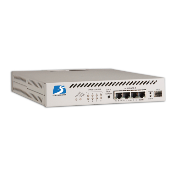
Ethernet Data Connections (See Figure 5)
Attach Ethernet data cables to any of the four 10/100BaseT
RJ45 plugs on the front panel or insert an SFP module in the
front panel slot. Generally, any 100BaseFX or 1000BaseX
SFP module is compatible; contact Aktino Customer Service
with any question regarding SFP compatibility.
Caution In order to comply with the intrabuilding lightning
surge requirements, intrabuilding Ethernet wiring must be
shielded, and the shield for the wiring must be grounded at
both ends.
AK500 Ethernet Compact Remote Units
AK500 Ethernet Compact Remote Unit
Quick Installation
CLEI Code
COM9S10E
COM9T10E
Figure 1 Rack Bracket Mounting
Figure 2 Rack Flange Mounting
Figure 3 Wall Mounting
1
Part #
Description
AKCURB
Dual Compact Unit Rack Bracket
AKCUWB
Compact Unit Wall Mount Bracket
AKCUF19
Compact Unit 19 inch rack flange mounts
AKCUF23
Compact Unit 23 inch rack flange mounts
AKRUPA
Compact RT Unit AC adapter
Document 180-0035-001 R04
Advertisement

Summary of Contents for Aktino AK500
- Page 1 1RU high brackets for 19” and 23” racks or can be wall mounted with the optional wall mount bracket. The Compact Remote Unit is either locally powered or line powered by the Central Office Compact Unit or Line Card. Aktino products utilize the technology “MIMO on DMT”...
- Page 2 Aktino unit. The default user name and password is “superuser” (case sensitive). 5) If desired, the Aktino units can now be monitored with AktinoView. The Compact Remote Unit provides read only capability only, system parameters cannot be change.
- Page 3 AktinoView V3 uses the front panel MGMT Ethernet port system. Performance monitoring for Ethernet, MSPAN, and for access to the Aktino unit. AktinoView V3 should be Pair is available through the tabs. Current system alarms started verify the health of the circuit. The default user name (see Table 3) are displayed on the main status screen.
Need help?
Do you have a question about the AK500 and is the answer not in the manual?
Questions and answers