Table of Contents
Advertisement
Scope
This manual contains information concerning the installation, operation and maintenance
of the Vantage 2210/2220. To ensure proper performance of the unit, the instructions
should be thoroughly understood and followed.
Keep the manual in a readily accessible location for future reference.
Changes and additions to the original edition of this manual will be covered by a
"CHANGE NOTICE" supplied with the manual. The change notice will identify the sections in this
manual where the changes have occurred.
General Specifications............................................................................................................
General Description................................................................................................................
Installation Procedure..........................................................................................................
Enclosure Mounting ...............................................................................................................
Sensor Mounting ....................................................................................................................
Wiring Connections................................................................................................................
Splice Procedure.....................................................................................................................
Programming ........................................................................................................................
QuikCal Menu Functions .......................................................................................................
Program .............................................................................................................................
Level Mode ......................................................................................................................
Flow Mode.......................................................................................................................
Totalizer ...........................................................................................................................
4-20 Output ......................................................................................................................
Setpoints...........................................................................................................................
Sensor Calibration............................................................................................................
Damping...........................................................................................................................
Lost Echo .........................................................................................................................
Flow Simulation...............................................................................................................
Integrator..........................................................................................................................
Pump Alternation .............................................................................................................
Relay Assignment ............................................................................................................
Status ..................................................................................................................................
Data Logger .......................................................................................................................
System Setup...................................................................................................................... 3-10
Calibration ......................................................................................................................... 3-11
Sensor Mounting for Primary Elements ............................................................................ 3-12
Parts List ............................................................................................................................... 3-17
Vantage Series 2200
Vantage 2210/2220
Table of Contents
1-1
Section
1
1-2
1-3
2-1
2-1
2-2
2-4
2-6
3-1
3-1
3-2
3-2
3-3
3-5
3-6
3-6
3-6
3-7
3-7
3-7
3-7
3-7
3-8
3-8
3-9
942001Rev
1.06 04/07
Advertisement
Table of Contents

Summary of Contents for Eastech Flow Controls Vantage 2210
-
Page 1: Table Of Contents
Scope This manual contains information concerning the installation, operation and maintenance of the Vantage 2210/2220. To ensure proper performance of the unit, the instructions should be thoroughly understood and followed. Keep the manual in a readily accessible location for future reference. -
Page 2: General Specifications
General Specifications FB5: 0 to 25 feet. Maximum total range including offset distance is 26 feet. Minimum offset 1 foot. FB7: 0 to 15 feet. Maximum total range including offset distance is 16 feet. Span Range Minimum offset 1 foot. FB3: 0 to 50 feet. -
Page 3: General Description
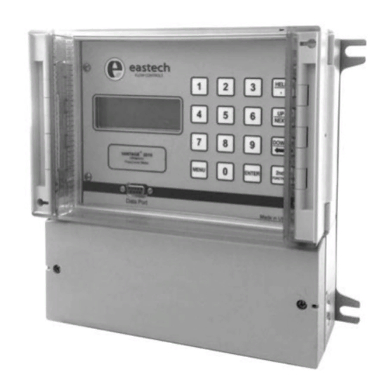
General Description The following description applies to both the Vantage 2210 and 2220. The Vantage series 2200 is an ultrasonic level/flow meter. Its' design allows it to be easily programmed as a level meter or an open channel flow meter. It can operate two ultrasonic sensors and can be programmed for two level applications, two flow applications or one level and one flow application. -
Page 4: Enclosure Mounting
Section Installation Enclosure Mounting The enclosure is rated IP 66 (NEMA 4X). A sunshade is recommended for outdoor installation. There are two stainless steel mounting brackets factory assembled to the enclosure. The mounting feet have slots for ¼" bolts (4 places). The electronics should be mounted with the display at eye level or lower. There are three ½... -
Page 5: Sensor Mounting
Sensor Mounting Bracket Dimensions: 4.00" 2.75" The Vantage series 2200 is supplied with a stainless steel mounting bracket. The mounting bracket should .38" be leveled in both plains. The 2200 sensor will be 1.88" mounted to the 1 inch hole in the mounting bracket. 3.00"... - Page 6 1" NPT FB3 Sensor Dimensions: The FB3 sensor is used for applications where the maximum level is 50 feet. (See Specifications Page 5.50" 1-2.) There is a 1 inch NPT threaded nipple on top of the sensor for mounting on bracket or customer 3.25"...
- Page 7 Sensor Wiring All of the terminal connections for the output signals are depicted in the drawing. The wiring connections are also on the inside of the enclosure terminal access cover. Green LED Indicates ac power is applied Fuse, Fuse, 4-20ma + 4-20ma - Relay 2 Relay 1...
- Page 8 Inserted Components: There may be a component added to the terminal strips on the Compensator inputs. The component size and type is determined by various Cable lengths and the style of sensor chosen. For cable lengths 5 to 150ft A 6800pf capacitor will be installed on terminals 5 & 7 for a single sensor. For Single Sensor: The component will be attached to Row A, Terminals 5 &...
-
Page 9: Splice Procedure
2200 sensor has 2 twisted pairs with shields around each pair and a shield around both pairs. Eastech Flow Controls Inc. splice kit part number is 544700-0001 which will include butt splice connectors and coax seal strips. Prepare the sensor end wire and the wire to be spliced per the following instructions. -
Page 10: Quikcal Menu Functions
Section QuikCal Menu Functions The screen to the left represents the normal screen. Up to eight lines may be assigned to the normal screen. Pressing the UP/Next Flw1 00 GPM key will switch to the second four lines and back. To program, 00x10 GAL recalibrate or change any function in the Vantage series 2200, Lvl1... -
Page 11: Program
>2) Program Programming for Level/Volume Applications From the main screen press the MENU key, then the number 02 keys. Program/Cal. Enter Security ID (00000000 from the factory), press the ENTER key 01)Level/Vol and then the number 01 key. The screen to the left will be visible on 02)Flow the display. -
Page 12: Totalizer
>2) Program Continued Programming for Flow Applications From the main screen press the MENU key, then the number 02 keys. Program/Cal. Enter Security ID (00000000 from the factory), then press the ENTER 01)Level/Vol key and then the 02 keys. The Level Units screen will be visible on the 02)Flow display. - Page 13 >2) Program Continued >02)Weirs 01) V-Notch 1) 11.25 degree 4) 45 degree 2) 22.5 degree 5) 60 degree 3) 30 degree 6) 90 degree 2) Contracted 1) 12 inch 5) 36 inch 9) 96 inch 2) 18 inch 6) 48 inch 10) 120 inch 3) 24 inch 7) 60 inch...
- Page 14 >2) Program Continued Once the primary element type and size is selected the screen at Flow Primary Element the left will appear. This screen displays the Maximum flow of Max Flow ***.** the Primary Element, the suggested VMt (vertical mounting VMt= **.** distance of the bottom of the sensor to zero flow, and the HMt...
-
Page 15: Setpoints
>02) Program Continued 4-20 Output Assignment and Adjustment 04) 4-20 Out Selection 4 in the programming menu is the 4-20mA output and assignment adjustment. Press the 04 key to adjust or assign the 4-20mA DC output. 1) Adjustment: To adjust or calibrate the 4-20mA DC output press the 01 key. -
Page 16: Damping
>02) Program Continued Output Damping Adjustment To adjust the 4-20mA output damping press the 07 keys. This will allow the 07) Damping user to adjust the damping time. The damping times available are: 01) None 05) 60 Seconds 02) 5 Seconds 06) 2 Minutes 03) 15 Seconds 07) 4 Minutes... -
Page 17: Relay Assignment
>02) Program Continued The first screen is for Setpoint Position #1. Select the number corresponding 11) Pump Alt. to the setpoint desired. After the selection, the next setpoint position will be shown. After the setpoint position #3 is selected, the relay position screen will be shown. -
Page 18: Data Logger
>03) Status Continued 05) History: View logged data in graphic form for each of the eight channels available to log. Select the channel to be viewed by pressing the number on the keypad. Press the UP or DOWN key to scroll through the data. 06) Daily Sum: View the Average, Minimum and Maximum flows and the time of the event for the last eight days of flow. -
Page 19: System Setup
>05 System Setup The system setup option will allow the user to set up the Vantage series 2200 >05) System Setup for the following options. 01) Language: This will allow the user to select the language displayed in the Vantage series 2200. The options are 01) English, 02) German, 03) Spanish. -
Page 20: Calibration
>6 Calibration The next option in the programming menu is Calibration. The options >06) available in the Calibration menu are: Calibration 01) Flow Simulation: The flow simulation screen will allow the user to check the flow curve programmed into the unit. Enter the flow level in the engineering units displayed. - Page 21 Sensor Vertical and Horizontal Mounting References PARSHALL FLUMES Top View Side View V Mt Flow H Mt Size H Dim. Vcal Full Scale (GPM) Full Scale Head Rise (in.) (in.) (in.) Min. Max. Max (in.) 11.00 21.46 9.46 12.00 30.21 18.21 16.00 30.29...
- Page 22 PALMER BOWLUS FLUMES Side View V Mt Flow H Mt Top View Size H Dim. Vcal Full Scale (GPM) Full Scale Head Rise (in.) (in.) (in.) Min. Max. Max (in.) 3.00 17.16 5.16 4.00 18.77 6.77 5.00 20.46 8.46 6.00 22.15 1100 10.15...
- Page 23 TRAPEZOIDAL FLUMES Top View H Mt Flow Front View V Mt H FLUMES VIEW H Mt Front View Flow V Mt Vantage Series 2200 3-14...
- Page 24 WEIRS Side Top View H Mt View Weir V Mt Plate Weir Pl Weir Zero Crest RECTANGULAR WEIR WITH END CONNECTIONS Size H Dim. Vcal Full Scale (GPM) Full Scale Head Rise (in.) (in.) (in.) Min. Max. Max (in.) 19.96 7.96 24.71 2100...
- Page 25 OPEN FLOW NOZZLES H Mt V Mt H Mt V Mt Size H Dim. Vcal Full Scale (GPM) Full Scale Head Rise (in.) (in.) (in.) Min. Max. Max (in.) 21.00 16.79 4.79 23.00 18.66 6.66 25.00 20.77 8.77 29.00 21.55 1100 9.55 31.00...
-
Page 26: Parts List
Vantage series 2200 Parts List PART NUMBER DESCRIPTION 544717-0001 2210 Electronics W/Enclosure 544716-0001 2220 Electronics W/Enclosure 528076-0001 Sensor Mounting Bracket (All FBs) 544776-0005 FB5A Sensor Head W/30 Feet Cable (Flow/Level) 544776-0006 FB5B Sensor Head W/100 Feet Cable (Flow/Level) 544776-0007 FB5C Sensor Head W/300 Feet Cable (Flow/Level) T B A FB7A Sensor Head W/30 Feet Cable (Flow/Level) T B A... - Page 27 A claim for equipment damaged in transit is the sole responsibility of the customer. NUCLEAR DISCLAIMER Equipment sold by Eastech Flow Controls Inc. is not intended for use in connection with any nuclear facility or activity unless covered by a specific quotation where the conditions of such usage will be detailed. If equipment is used in a nuclear facility or activity without a supporting quotation, Eastech Flow Controls Inc.
Need help?
Do you have a question about the Vantage 2210 and is the answer not in the manual?
Questions and answers