
Subscribe to Our Youtube Channel
Summary of Contents for DEXTER AXLE E/H 1000
- Page 1 ERVICE ANUAL EXTER E/H 1000 & 1600 RAKE CTUATORS www.dexteraxle.com www.dexteraxle.com www.dexteraxle.com www.dexteraxle.com www.dexteraxle.com...
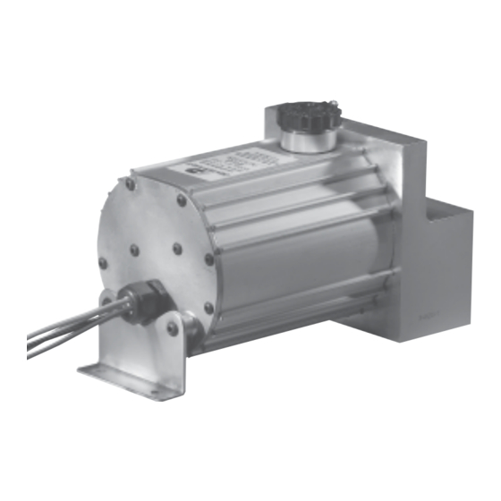
- Page 2 Introduction This manual has been provided to guide you through the process of installing, operating, and maintaining your Dexter E/H 1000 or E/H 1600 hydraulic brake system actuator. This electrically powered unit has been designed and manufactured to give safe, reliable power to your hydraulic trailer brakes.
-
Page 3: Table Of Contents
Contents Installation Instructions ............. 3 Getting Started ..............3 Electrical Installation Requirements ......... 6 Wire Colors and Function ..........6 Test Electrical Operation ............9 Bleeding and Brake Adjustment ..........10 Testing and Adjustment of Controller Unit ......12 Troubleshooting Guide ............13 Warranty ................. -
Page 4: Installation Instructions
CAUTION This is the safety alert symbol. It is used to alert you to potential injury hazards. Obey all safety messages that follow this symbol to avoid possible injury or death. Actuator Installation Instructions Getting Started The following materials are required to properly install the Dexter E/H unit. - Page 5 Failure to protect the actuator from damage can cause the unit to malfunction and void the Dexter Axle warranty. Mounting consideration should be given to the following: 1. The unit must be level, with the filler neck up.
- Page 6 CAUTION Always use new DOT 3 or DOT 4 brake fluid from a sealed container. Never attempt to reuse old or dirty fluid. Do not overfill the unit. Take care to protect painted surfaces from contact with the brake fluid. Wash off any spilled brake fluid.
-
Page 7: Electrical Installation Requirements
Electrical Installation Requirements CAUTION Undersized wire will increase electrical resistance and will prevent proper operation of this unit. Wire Colors and Function BLACK – 30 amp 12 volt Supply From Tow Vehicle* BLUE – Output From In-Cab Electronic Brake Controller WHITE –... - Page 8 It is the responsibility of the end user to ensure that their in-cab electronic controller is compatible with the Dexter E/H actuator. Dexter Axle attempts to provide compatibility with most controllers available, but is unable to anticipate design changes that might be introduced by the various controller manufacturers.
- Page 9 Note: If the Dexter E/H unit is wired to an on-board trailer battery instead of a conventional breakaway battery, the unit will draw a small amount of current even when not in use. Prolonged periods of non-use (with no recharging) can deplete an on-board battery.
-
Page 10: Test Electrical Operation
Test Electrical Operation 1. Attach the trailer to the towing vehicle. Do not connect trailer plug to tow vehicle until step #2 is completed. 2. Pull the breakaway switch. The Dexter E/H unit should run. If the unit does not run, check breakaway battery condition and system wiring. -
Page 11: Bleeding And Brake Adjustment
Bleeding and Brake Adjustment 1. It typically is much easier to bleed the brakes with two people working together. 2. Special care must be taken to insure that the Dexter E/H unit does not run out of brake fluid. Check the fluid level frequently during the bleeding process. - Page 12 12. Install plastic tubing onto the bleeder screw of the wheel cylinder/caliper. 13. Immerse the free end of the plastic tube in a clean container partially filled with brake fluid. 14. Open the bleeder screw one half turn on the wheel cylinder/caliper farthest from the Dexter E/H unit.
-
Page 13: Testing And Adjustment Of Controller Unit
Testing and Adjustment of Electronic Controller Unit 1. Adjust the gain setting on the in-cab controller to a mid range setting. 2. Drive vehicle at 10 to 15 m.p.h.. 3. Apply the brakes. If braking is too severe, adjust the gain setting down to decrease pressure and retest. -
Page 14: Troubleshooting Guide
GROUND WIRE RUNS DIRECTLY TO THE TOW VEHICLE’S BATTERY GROUND. NO EXCEPTIONS. 7. Detach all wires from the Dexter Axle E/H unit leaving only the blue, black, white, and yellow wires. It is important that the unit is disconnected from any other wires going to the towing vehicle or breakaway switch and breakaway battery. - Page 15 13. If this does not occur, the unit may be defective. 14. Leave the white wire connected to the negative (-) terminal of the battery. 15. Connect only the yellow wire to the positive (+) terminal of the battery. 16. The motor should run and the unit should pressurize. 17.
- Page 16 Trailer brakes not aggressive enough 1. Increase the gain setting on the in-cab electronic brake controller. 2. Check brake adjustment. -15-...
- Page 17 EXCLUSIVE REMEDY Dexter Axle will, at its option, repair or replace the affected components of any defective axle, repair or replace the entire defective axle, or refund the then-current list price of the axle. In all cases, a reasonable time period must be allowed for warranty repairs to be completed.
- Page 18 12. Improper wheel nut torque. 13. Cosmetic finish or corrosion. LIMITATIONS In all cases, Dexter Axle reserves the right to fully satisfy its obligations under the Limited Warranties by refunding the then-current list price of the defective axle (or, if the axle has been discontinued, of the most nearly comparable current product).
-
Page 19: Warranty
Some states do not allow limitations on how long an implied warranty lasts, or the exclusion or limitation of incidental or consequential damages, so the above exclusion or limitation may not apply to you. Inquiries regarding these warranties should be sent to: Dexter Axle P.O. Box 250 Elkhart, Indiana 46515 -18-... - Page 20 Service Record Date Service Performed Mileage -19-...
- Page 21 Service Record Date Service Performed Mileage -20-...
- Page 22 Service Record Date Service Performed Mileage -21-...
- Page 23 Elkhart, IN 46516 Fax (574) 295-8666 Ph (574) 295-7888 NO PART OF THIS CATALOG MAY BE REPRODUCED WITHOUT DEXTER AXLE'S PERMISSION. ALL PART NUMBERS, DIMENSIONS AND SPECIFICATIONS IN THIS CATALOG ARE SUBJECT TO CHANGE WITHOUT NOTICE. © Dexter Axle 2006...
Need help?
Do you have a question about the E/H 1000 and is the answer not in the manual?
Questions and answers