
Related Manuals for Aurea T Series


Summary of Contents for Aurea T Series
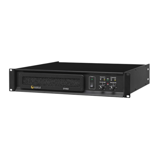
- Page 1 T Series (Series 2) OPERATING INSTRUCTIONS (DT 450/CT 160 LINE) Proud Technology Partner of...
-
Page 2: Technical Specification
TECHNICAL SPECIFICATION DT 450 CT 160 Parameter (Units) Output Power (per channel) (Watts) 8 ohms 4 ohms 2 ohms 1150 Output Power (bridged) (Watts) 8 ohms 1500 4 ohms 2300 THD+N: (%)(4 ohms) @1kHz(@1dB below max output power)< 0.008 0.008 @20Hz to 20kHz(@3dB below max output power)<... -
Page 3: Installation: Electrical
INTRODUCTION Your T Series power amplifier is a no compromise, high quality, class AB power amplifier. There is no dynamic switching of the audio or power rails (a very common method of achieving extra power at the expense of audio quality) thus ensuring optimum sonic performance. - Page 4 WARNING: Apparatus with CLASS I construction shall be connected to a MAINS socket outlet with a protective earthing connection. WARNING: To prevent injury, this apparatus must be securely attached to the rack in accordance with the installation instructions. Read these instructions. 14.
-
Page 5: Installation
INSTALLATION: MECHANICAL To ensure that this equipment performs to specification, it should be mounted in a suitable rack or enclosure as described below. Like all high power amplifiers, it should be kept away from other equipment which is sensitive to magnetic fields. -
Page 6: Operation
2 - Additionally Channel A Speakon connector carries Channel B output on Pins +2 & -2 to allow easy bi-amping or bridged operation. HOT Pin COLD Pin CONFIGURATION 2 DOES NOT APPLY TO CT 160 (See also Bridged operation) NOTE: 1. -
Page 7: Panel Controls And Indicators
These are active from a minimum output level of approximately 1 Watt and are an indication only of signal presence. Limiters (amber LED) The T Series amplifiers incorporate signal limiters, which are preset to prevent clipping with high levels of drive. The amber LEDs on the front panel illuminate to indicate operation of the limiters. - Page 8 (ENSURE THAT ELECTRICAL POWER TO THE UNIT IS DISCONNECTED BEFORE CARRYING OUT ANY MAINTENANCE.) The filter behind the air intake apertures on the front of T Series amplifiers should be cleaned or replaced periodically, e.g. 12-24 months. (Filters in amplifiers located in more 'dirty' atmospheres may require more frequent maintenance).
- Page 9 The rear of the unit is adequately supported. The brackets which are supplied fit standard 19 inch (483mm) rack mounting systems. THE FRONT PANEL IS NOT CAPABLE OF SUPPORTING THE UNIT ON ITS OWN. (The general T Series safety warnings, precautions and service advice also apply to the DT LINE.)
- Page 10 APPENDIX II Instructions for using 'DT' series amplifiers with 100V/70V line transformers Frequency response It is necessary to provide some low frequency roll off to prevent the possibility of the line transformer saturating. On the CD 160 we recommend using an crossover filter PCB – XO5 (each XO5 card handles 2 channels) normally set to a crossover frequency of 63 Hz.
Need help?
Do you have a question about the T Series and is the answer not in the manual?
Questions and answers