Table of Contents
Advertisement
Quick Links
Advertisement
Table of Contents

Summary of Contents for E-TRAK/R 5000
- Page 1 RDF Pulse and GPS Enhanced Tracking System...
-
Page 2: Warranty
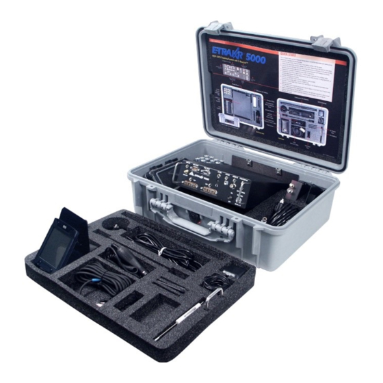
You can also contact the FCC using their FAX back service at: (888) 418-3676 trademarks Additional instructions are available by Trademarks telephone at: (888) 225-5322 include: The filing fee form is returned to: • E-TRAK/R ® Federal Communications Commission ® • MiniPIX ® 1270 Fairfield Road • DynaPIX... - Page 3 OVERVIEW E-Beacon EVB Series Beacon Batteries Access Panel Introduction The E-TRAK/R 5000 is a combination RDF (Radio Direction Finding) and GPS tracking and locating system. RDF pulse technology is Magnet used to conserve beacon battery life and track Plate at long ranges. GPS technology is used to precisely locate both the tracking vehicle and the target beacon.
- Page 4 Styli (3) Formats • Wireless Enabled PDA (Control Head) Screwdriver • PDA Data Interface • GPS data from E-Beacon and E-TRAK/R • 10 Watt VHF, 220 MHz or UHF Command Transmitter • Auxiliary RS-232 Interface for PDA Belt Clip programming, and mapping interface PDA Interface Cable •...
-
Page 5: Quick Start
4 Connect the AA5 Covert Antenna Array to the connector labeled UHF or VHF on the front panel of the E-TRAK/R 5000 (depending on the band you are using). Note that the GPS antenna is also built into the AA5. - Page 6 Command TX Antenna to the CMND TX connector on the front panel of the E-TRAK/R 5000. 7 Connect DC Power to the E-TRAK/R 5000. A DC power cable is provided, which connects to a conditioned power input labeled 10-32 VDC on the front panel of the E-TRAK/R 5000. Connect the cable to 10 to 32 VDC vehicular power.
- Page 7 Channel frequencies for Exact Model May Differ your E-TRAK/R can be modified in the Preferences Menu (see Channel Settings page 19 for more information.) 13 Select the Tracking Mode you want to use - RDF Tracking or GPS Tracking.
- Page 8 COMPONENTS E-TRAK/R 5000 Front Panel Command Battery Status Data Transmitter Power Wireless Output Serial Port for PDA PDA Power Out GPS Antenna VHF Receiver UHF Receiver Command ON/OFF DC Power Connector Antenna Antenna Transmitter Switch Connector Connector Connector Antenna Connector...
- Page 9 LED displays RED when vehicle power is not available and the internal backup battery is supplying power. WARNING: when using the E-TRAK/R in an aircraft the supplied antenna terminator must be BATT STATUS LED installed on the Command TX Connector.
-
Page 10: Back Panel
COMPONENTS Auxiliary Connector GPS LED Data Output. The GPS LED displays when the E-TRAK/R GPS is operational. PDA Port The PDA Port is the GPS Antenna Connector RS-232 link for the The GPS Antenna Connector attaches to the PDA Control Head GPS receiver antenna cable. -
Page 11: Operation
Use one or the other to dim display, not both. Software Controls All of the E-TRAK/R capabilities are available through the touch screen Control Head with PDA Interface Cable soft controls. Use the stylus provided to make selections on the display and Protective Case screen. - Page 12 OPERATION Display Screen Interface - Control Head See Descriptions Mission Channel starting on page 16 Name Number Channel Selector Filtered (Averaged Bearing) 171.600 MHz Fil. ON/OFF Bearing History Averaged Bearing Receiver Signal Strength Indicator Instantaneous Bearing Blue = RAW Bearing Red or Yellow = GPS Pointer Beacon Pulse Indicator Communication Link...
- Page 13 Hour Glass = Transferring Communication Link Status Indicator: Icon represents status of mission parameters communication between Control Head and E-TRAK/R receiver for either cabled or wireless link. NOTE: For information on wireless “paired” settings between the E-TRAK/R and PDA Control Head see page 25.
- Page 14 • GPS Track commands the beacon to send GPS coordinates to the Tracker Tracker E-TRAK/R. When changing channels you do not have to reset the GPS mode. GPS data transfer from the beacon uses more power than simple Mute Tracker RDF pulse tones, thus reducing battery life of the beacon.
- Page 15 OPERATION Motion Icons Motion Indicator: This icon changes depending on condition of movement of the beacon. WHEEL, NO movement = • Rotating Wheel indicates beacon is moving. Stopped, beacon pulse • Stationary Wheel indicates momentary stopped condition of beacon. once every two seconds Pulse rate drops to once every 2 seconds.
- Page 16 FREQUENCY allows make sure the 10W Command you to edit the frequency of the E-TRAK/R receiver, and set it for the Transmitter is terminated at the channel number you want. NAME allows you to enter alphanumeric text to antenna connection.
- Page 17 GPS Antenna. 3 Connect the NMEA Data Recording device to the RS-232 AUX PORT on the front panel of the E-TRAK/R. Be sure to supply the necessary power to operate this device. 4 Apply 10-32 VDC power to front panel of the E-TRAK/R. The PWR STATUS LED will be green with applied power.
- Page 18 If Control Head needs to synchronize with the E-TRAK/R it may restart itself. 7 Turn the E-TRAK/R Power Switch ON. The POWER LED will be illumi- nated when power is connected. The communication Link icon on the PDA display indicates the status during start-up. When it turns to a solid green square you are ready to setup the system.
-
Page 19: Operation Notes
In a situation where several E-TRAK/R’s will be used in close proximity (such as a training exercise), be sure to turn on one E-TRAK/R and one PDA at a time to establish a paired wireless connection. Otherwise cross communication may happen. - Page 20 • Ambient RF noise level tracking are essential. • Electrical or vehicular ignition This section is designed to familiarize you with the E-TRAK/R PDA Control noise Head display, its functions, and how to read the graphical representations. • Topographic features, such as Knowing how to interpret this information can help keep you on track.
- Page 21 OPERATION Tracking with the Control Head Display 171.600 MHz 171.600 MHz 171.600 MHz Fil. Fil. Got valid GPS data Mute Tracker Mute Tracker Mute Tracker Radio Direction Finding (RDF) Radio Direction Finding (RDF) RDF and Global Positioning Filtered Mode Raw Mode System (GPS) Mode Bearing History (grey pie shape) is Bearing History (grey pie shape) is...
- Page 22 171.600 MHz keeps the tracking vehicle out of the target vehicles sight while maintaining relatively reliable two-way communications REFLECTION between the E-TRAK/R and the E-beacon. This distance may OFF BUILDING TARGET BEACON be significantly less in urban environments and areas of high RF ambient noise.
- Page 23 OPERATION In any tracking environment, the GPS update rate of the beacon will have 171.600 MHz Fil. an effect on the accuracy of the displayed target bearing. When both vehicles are moving and the tracking vehicle is following too close, a display indicating RDF bearing straight ahead and a GPS bearing of straight behind may be generated (Figure 3).
- Page 24 OPERATION The GPS arrow turns yellow and average bearing bar indicator turns red 171.600 MHz Fil. when 2 or more reported GPS coordinates have been missed. A yellow arrow indicating last known GPS reference is a perfectly valid waypoint for users to seek.
- Page 25 Range - will you ever need to rely on the ultimate range of the E-TRAK/R? Yes - but usually this is only when something unexpected has happened such as the target getting on the freeway and heading away at a rapid speed.
- Page 26 RSSI provides a level of confidence for each received signal. Signals Can Be Misleading A characteristic of the E-TRAK/R system is its “damping” effect on signals received as widely divergent. Some radio finding systems exhibit wide swings in bearing indicators when presented with reflection situa- tions.
- Page 27 Multiple Signal Reception The receiving units of the E-TRAK/R system will pick up all signals within its range of sensitivity. It would be rare for it to pick up another unit operating in your vicinity. It is more likely that it will pick up secondary signals from your tracking operation.
- Page 28 E-TRAK/R system can be extended to several miles. The high ground doesn’t have to be the highest point in the area since this could expose the tracker to other interference.
- Page 29 NOTES...
-
Page 30: Two Year Warranty
TWO YEAR WARRANTY warrants its RF transmitting and receiving products to be free from defects in workmanship or material for a period of two (2) years from the date of shipment unless otherwise stated. The liability under this warranty is limited to replacing, repairing, or issuing credit, at option, for any products, which are returned by the purchaser during such warranty period, provided: is notified and a Repair Authorization Number is issued by Customer Service within 30 days...
Need help?
Do you have a question about the 5000 and is the answer not in the manual?
Questions and answers