
Summary of Contents for Echoring ER-EB 1000M
- Page 1 ECHORING ETHERNET BRIDGE User Manual ER-EB 1000M (US/CA Version) r20.10 Contact Information: R3 – Reliable Realtime Radio Communications GmbH Bismarckstraße 10-12, 10625 Berlin www.r3.group/contact...
- Page 2 UM-ER-EB1000M-1-20210315-US © by R3 – Reliable Real-time Radio...
-
Page 3: Table Of Contents
UM-ER-EB1000M-1-20210315-US Table of Contents General Terms of Use of this Document ........Please Observe the Following Notes . - Page 4 UM-ER-EB1000M-1-20210315-US © by R3 – Reliable Real-time Radio...
-
Page 5: General Terms Of Use Of This Document
UM-ER-EB1000M-1-20210315-US 1 General Terms of Use of this Document It is the user’s responsibility to check regularly and ensure they have downloaded the latest version of this manual, as R3 may edit, revise, or improve product documentation over time. The user must ensure the product is used correctly according to this document’s guidelines, in particular observing all relevant standards and regulations. -
Page 6: Please Observe The Following Notes
UM-ER-EB1000M-1-20210315-US 2 Please Observe the Following Notes Please observe and obey following note formats and instructions throughout the document: TIP — Text in this format is information explaining the use of the product. ATTENTION — Text in this format must be observed in order to avoid malfunction and/or even damage, or to avoid security risks. -
Page 7: Product Information
3.1 General Information 3.1.1 Localization Information and Constraints The EchoRing Ethernet Bridge ER-EB 1000M (Version for USA and Canada) was specifically designed to meet regulatory requirements of the FCC and ISED respectively. The Device operates in the 5GHz Band, more specifically Channels 36, 40, 44, 48, 149, 153, 157, 161 and 165. -
Page 8: Intended Use Of The Product
3.2 Intended Use of the Product The EchoRing Ethernet Bridge (device) enables a time-critical and reliable wireless link between Ethernet-based industrial protocol devices. It can be employed for: •... -
Page 9: Needed Equipment
USB/Ethernet Adapter USB/MicroUSB Cable USB Wall Charger Components that are included when buying the EchoRing Ethernet Bridge separately. Components that are included when buying the Rollout Kit. * Item not needed in case Power over Ethernet (PoE) is used. Note that delivered switch in Rollout Kit does not support PoE. -
Page 10: Requirements On The Equipment
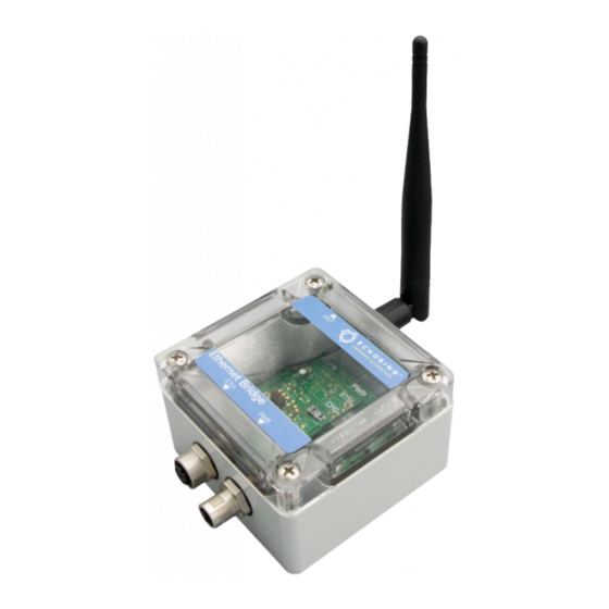
UM-ER-EB1000M-1-20210315-US 3.3.1 Requirements on the Equipment Item Requirements Ethernet Cable M12/RJ45 The signal cable for digital input must be carried in the same cable as the power supply and functional ground if the line length exceeds 3 meters. Switch Possibility to disable IGMP Snooping, at least as many ports as EREBs should be connected + 2 3.4 Connectors Figure 3-I: Connectors... -
Page 11: Led Indicators
UM-ER-EB1000M-1-20210315-US 3.5 LED Indicators Color/pattern Meaning • No power. • Green Device is powered on. • No traffic. • Green flashing Traffic (data) is being sent through the device. • Device is in operational mode. • Green Device is in configuration mode. •... -
Page 12: Configure The Device
Chrome (version 64 or newer). Other browsers may not support full functionality. 5. Power on the EchoRing Ethernet Bridges. TIP — Power on the EchoRing Ethernet Bridges one after another and note which one has which IP address. You will need that in Section 4.3 for step 4. -
Page 13: Configure The Device
1. Set up and access the Web User Interface (see Section 4.2). 2. In Web User Interface, take a look at ”Echoring Deployment”. Connected devices are shown in the paring view there. Click the IP address to pair all devices or click each device to include/exclude it. - Page 14 If no prioritized traffic is set, all data is treated as equally critical. 7. Click the EchoRing tab and set the parameters to match the application data and the wireless settings.
- Page 15 UM-ER-EB1000M-1-20210315-US TIP — To ensure the network can facilitate the application traffic’s cycle time, packet length and data rate, begin with setting lower reliability, then increase as necessary after all other parameters have been set. Optimize For: optimize the network for one of three parameters: Reliability (C), Packet Length (F) or Latency (G).
-
Page 16: Installation
UM-ER-EB1000M-1-20210315-US 5 Installation ATTENTION — The device emits RF energy in the ISM (Industrial, Scientific, Medical) band. Make sure that all medical devices used in proximity to this device meet appropriate susceptibility specifications for this type of RF energy. ATTENTION — The device is recommended for use in industrial environments. It is mandatory to employ a functional ground connection to comply with safety requirements. -
Page 17: Wall Or Mast Mounting
Please visit www.r3.group and download registration form found on the page ”Downloads”. 1. Arrange and connect a PC, the R3 Configuration Server 5 and the EchoRing Ethernet Bridges 1 to the switch 4 , according to Figure 7-I. Make sure that the internal ethernet connection of the R3 Configuration Server is connected to the switch and the USB ethernet adapter 7 of the R3 Configuration Server is connected to the internet. - Page 18 255.255.254.0 and apply. 4. Open a web browser and enter the URL http://172.30.0.1. 5. Power on the EchoRing Ethernet Bridges and wait until they show up in the Web User Interface. 6. Click the IP address to update all devices or click the devices that you want to update individually.
Need help?
Do you have a question about the ER-EB 1000M and is the answer not in the manual?
Questions and answers