
Summary of Contents for Axxeron Hesch HE 5700
- Page 1 HE 5700 Pilot valve box Quick guide (Translation of Original German version) # 422691 | Version 1.1...
- Page 2 Imprint HESCH Industrie-Elektronik GmbH Boschstraße 8 31535 NEUSTADT, GERMANY Phone: +49 5032 9535-0 Fax: +49 5032 9535-99 Web: www.hesch-automation.com Email: info@hesch.de District Court Hanover HRB 111184 VAT.-Id. No. DE813919106 General Management: Werner Brandis Published by: HESCH Industrie-Elektronik GmbH, Documentation Department Copyrights ©...
-
Page 3: Table Of Contents
Table of contents LEGAL PROVISIONS ........................... 4 SAFETY INFORMATION ..........................5 ...................... 5 YMBOLS AND ASIC AFETY NSTRUCTIONS ............................6 IGNAL WORDS ....................6 AFETY IN THE INDIVIDUAL OPERATING PHASES ..........................7 PECIAL EGULATIONS TECHNICAL DATA ............................8 NAME PLATE ............................. 9 MOUNTING ............................ -
Page 4: Legal Provisions
Legal Provisions Manufacturer HESCH Industrie-Elektronik GmbH, Boschstraße 8, 31535 NEUSTADT, GERMANY. Intended use The pilot valve boxes can be operated within the operating and environmental conditions approved in this quick guide without impairing its safety. The manufacturer is not liable for improper use and any resulting personal injury or material damage;... -
Page 5: Safety Information
Safety Information Symbols and Basic Safety Instructions This chapter contains important safety regulations and notes. For protection against personal injury and material damage, it is necessary to read this chapter carefully before working with the device. Symbols used The following symbols are used in this manual. All safety instructions have a uniform structure. Personal Injury Warning! The severity of the danger is indicated by the respective signal word. -
Page 6: Signal Words
Signal words DANGER! Indicates an imminently hazardous high risk situation, which, if not avoided, will result in death or serious injury. WARNING! Indicates a potentially hazardous medium risk situation, which, if not avoided, could result in death or serious injury. CAUTION! Indicates a hazardous low risk situation, which, if not avoided, could result in minor or moderate injury. -
Page 7: Special Regulations
Power Connection! The electrical cables must be laid according to the respective national regulations (in Germany VDE 0100). The measuring cables must be laid separately from the power lines. Troubleshooting! At the beginning of troubleshooting, all possible sources of faults on additional devices or supply lines (measuring lines, wiring and downstream devices) should be taken into consideration. -
Page 8: Technical Data
Technical Data General Operating voltage 24 V DC According to DIN-EN 61010-1 Electrical safety Emitted interference: DIN EN 61000-6-4 Interference immunity: DIN EN 61000-6-2 display 4 or 10 LED for designating the triggered valve 151 mm x 125 mm x 90 mm (W x H x D) (2…4 valves) Housing dimensions 231 mm x 125 mm x 90 mm (W x H x D) (5…10 valves) Mounting... -
Page 9: Name Plate
Name plate The name plate is located on the left side of each pilot valve box. Position name plate HE 5700 Pilot valve box Quick guide # 422691 | Version 1.1... -
Page 10: Mounting
Mounting The pilot valve is designed for wall mounting. The ambient temperature at the installation site must not exceed the permissible temperature for operation (see chapter 3 Technical Data). Compliance with the special regulations is required (see chapter 2.3 Safety in the individual operating phases). - Page 11 Dimensions HE 5700 (5...10 valves) HE 5700 Pilot valve box Quick guide # 422691 | Version 1.1...
-
Page 12: Opening The Device
Opening the device Danger of Electrocution! Do not open the device when it is connected to the voltage! When opening the devices or removing covers and parts, live parts may be exposed. Connection points can also be live! Disconnect the device from the power supply! The opening and closing works without screws by means of hinge technology. -
Page 13: Display Elements
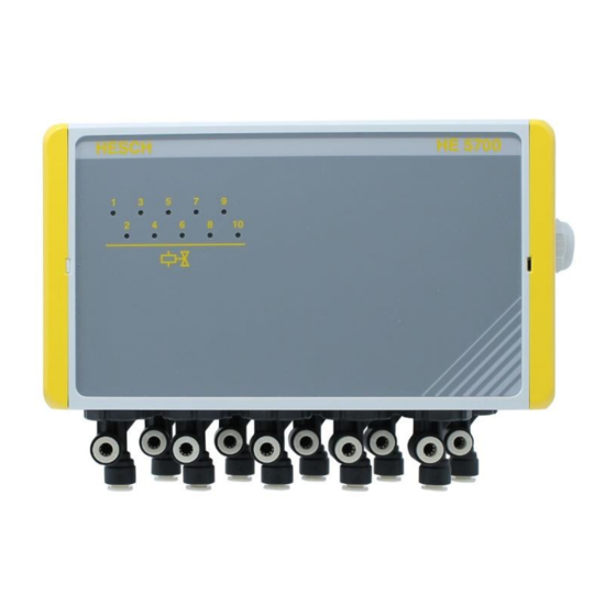
Display elements Display elements HE 5700 (on the left 2...4 valves, on the right 5...10 valves) 2 to 4 pilot valves maximum can be installed into the pilot valve box HE 5700 for 2...4 valves. 5 to 10 pilot valves maximum can be installed into the box for 5...10 valves. When triggering a valve, the respective LED lights up yellow (see Figure 5). -
Page 14: Electrical Commissioning
Electrical Commissioning Before switching on the device, observe the following safety instructions: Danger of Electrocution! Electrical installation must only be carried out when the power is disconnected. Danger of Electrocution! Work on the electronic parts may only be carried out by qualified personnel. - Page 15 Inside view HE 5700 (2...4 valves) Solenoid valve controller … … Connection to solenoid valve controller (2...4 valves) HE 5700 Pilot valve box Quick guide # 422691 | Version 1.1...
- Page 16 Inside view HE 5700 (5...10 valves) Solenoid valve controller … … … … … … … … Connection to solenoid valve controller (5...10 valves) HE 5700 Pilot valve box Quick guide # 422691 | Version 1.1...
-
Page 17: Control Air Connections On Solenoid Valve
Control air connections on solenoid valve Control air output Connection direction Control air input Control air output solenoid valve HE 5700 Pilot valve box Quick guide # 422691 | Version 1.1... -
Page 18: Maintenance And Disposal
Maintenance and disposal Maintenance, Repair The device must be cleaned regularly to prevent an increased generation of dust on the device. Disposal Dispatch metals and plastics for recycling. Electrical and electronic components must be collected separately and disposed of properly. Dispose of equipped circuit boards properly. HESCH Industrie-Elektronik GmbH Boschstraße 8 31535 NEUSTADT, GERMANY...
Need help?
Do you have a question about the Hesch HE 5700 and is the answer not in the manual?
Questions and answers