Advertisement
Quick Links
THIS INSTRUCTION BOOKLET CONTAINS IMPORTANT SAFETY INFORMATION. PLEASE READ AND KEEP FOR FUTURE REFERENCE.
Please give us a chance to make it right and do better!
Contact our friendly customer service department for help first.
Replacements for missing or damaged parts will be shipped ASAP!
USER'S MANUAL
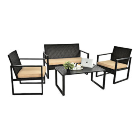
4 Pcs Wicker Sofa Set
GYM06499
FLOOR AREA
2MX2M
ASSEMBLED BY 2 ADULTS
Advertisement

Related Manuals for PATIOJOY GYM06499


Summary of Contents for PATIOJOY GYM06499
- Page 1 USER’S MANUAL 4 Pcs Wicker Sofa Set GYM06499 THIS INSTRUCTION BOOKLET CONTAINS IMPORTANT SAFETY INFORMATION. PLEASE READ AND KEEP FOR FUTURE REFERENCE. Please give us a chance to make it right and do better! FLOOR AREA 2MX2M Contact our friendly customer service department for help first.
-
Page 2: Before You Start
Contact Us! Do NOT return this item. Contact our friendly customer service department for help first. E-mail cs@gymaxservice.com Before You Start Read each step carefully before starting. It is very important to ensure each step followed in correct order, otherwise assembly difficulties may occur. Most of board parts are labeled or stamped on the raw edges. - Page 3 Not actual size Left Arm x 2 Right Arm x 2 Back x 2 Seat x 2 Cushion x 2...
- Page 4 Not actual size...
-
Page 5: Hardware List
Hardware List Actual size M6 x 15mm M6 x 25mm BOLT BOLT M6 x 35mm BOLT WASHER 4 x 4 ADJUSTABLE ALLEN WRENCH LEVELLERS... - Page 6 STEP 1 Insert adjustable levellers (O) to bottom of each Arm(A) by turning clockwise until secure. Adjust height as desired. Repeat step for the other side arm(B).
- Page 7 STEP 2 Attach the seat(D) to the arm (B) by inserting bolts (K & J) with washers (M) through the pre-drilled holes on the seat into the pre-welded nuts on the arm. Repeat step for the other side arm(A). assembly is completed.
- Page 8 STEP 3 Attached the back(C) to the seat (D) by inserting bolts (K) with washers (M). STEP 4 Attached the back(C) to the arm (A&B) by inserting bolts (I) with washers (M).
- Page 9 STEP 5 Tighten all the bolts with the allen wrench, and turn the chair to the upright position. place the seat cushions(P) onto the chair seat. Your chair is now ready for use.
-
Page 10: Maximum Loads
Maximum Loads 250 lbs This item is only suitable within the specified maximum load-bearing. Heavier loads than the indicated load capacity may cause instability, resulting in possible injuries. - Page 11 Not actual size Left Arm x 1 Right Arm x 1 Back x 1 Seat x 1 Cushion x 1...
- Page 12 Not actual size...
- Page 13 Hardware List Actual size M6 x 15mm M6 x 25mm BOLT BOLT M6 x 35mm BOLT WASHER 4 x 4 ADJUSTABLE ALLEN WRENCH LEVELLERS...
- Page 14 STEP 1 Insert adjustable levellers (O) to bottom of each Arm(A) by turning clockwise until secure. Adjust height as desired. Repeat step for the other side arm(B).
- Page 15 STEP 2 Attach the seat(F) to the arm (B) by inserting bolts (K & J) with washers (M) through the pre-drilled holes on the seat into the pre-welded nuts on the arm. Repeat step for the other side arm(A). assembly is completed.
- Page 16 STEP 3 Attached the back(E) to the seat (F) by inserting bolts (K) with washers (M). STEP 4 Attached the back(E) to the arm (A&B) by inserting bolts (I) with washers (M).
- Page 17 STEP 5 Tighten all the bolts with the allen wrench, and turn the chair to the upright position. place the seat cushions(Q) onto the chair seat. Your chair is now ready for use.
- Page 18 Maximum Loads 250 lbs 250 lbs This item is only suitable within the specified maximum load-bearing. Heavier loads than the indicated load capacity may cause instability, resulting in possible injuries.
- Page 19 Not actual size Table Top x 1 Table Leg x 2...
- Page 20 Not actual size...
- Page 21 Hardware List Actual size M6 x 15mm M6 x 30mm BOLT BOLT 4 x 4 ALLEN WRENCH WASHER ADJUSTABLE LEVELLERS...
- Page 22 STEP 1 Insert adjustable levellers (O) to bottom of each Table leg(H) by turning clockwise until secure. Adjust height as desired. Repeat step for the other side Table leg(H).
- Page 23 STEP 2 Attached the Table Leg(H) to the Table Top (G) by inserting bolts (L&I) with washers (M).
- Page 24 STEP 3 Tighten all the bolts with the allen wrench, and turn the table to the upright position. Your coffee table is now ready for use.
- Page 25 Maximum Loads 50 lbs This item is only suitable within the specified maximum load-bearing. Heavier loads than the indicated load capacity may cause instability, resulting in possible injuries.
-
Page 26: Care And Maintenance
Care and Maintenance Use a soft, clean cloth that will not scratch the surface when dusting. Use of furniture polish is not necessary. Should you choose to use polish, test first in an inconspicuous area. Using solvents of any kind on your furniture may damage the finish. Never use water to clean your furniture as it may cause damage to the finish.
Need help?
Do you have a question about the GYM06499 and is the answer not in the manual?
Questions and answers