Table of Contents
Advertisement
Quick Links
Advertisement
Table of Contents

Summary of Contents for OPTOTHERM Thermoscreen IS640
- Page 1 User Manual for Thermoscreen IS640 Infrared Fever Screening System...
- Page 2 CE Declaration of Conformity This is to certify that the Optotherm IS640 infrared camera has been designed and manufactured to meet the requirements, as applicable, of the EU-Directive: 2014/30/EU Electromagnetic Compatibility and the following harmonizing standards. The system consequently meets the requirements for the CE-mark.
- Page 3 This manual is copyrighted by Optotherm, Inc. with all rights reserved. Under the copyright laws, this manual may not be reproduced in any form, in whole or in part, without the prior written consent of Optotherm, Inc. © 2020 Optotherm, Inc.
-
Page 4: Table Of Contents
Table of Contents Introduction Document Conventions Defined Terms Applications and Features How It Works Thermoscreen Accessories Spring Singapore Requirements Site Setup Site Conditions Site Design Operator Training Manual Screening (Individual) Manual Screening (Continuous) Automated Screening (Single) Automated Screening (Multiple) Automated Screening (Self) Hardware Setup Unpacking Mounting the Camera Enclosure... - Page 5 Key Concepts Skin Offset Fever Threshold Measuring Internal Core Temperature Thermalyze Software Overview File Menu Setup Menu 6.3.1 Program Settings 6.3.2 User Preferences 6.3.3 Messages 6.3.4 Bad Pixel Replacement Thermal Camera Fever Screening 6.5.1 Visual Image 6.5.2 Screening Violations 6.5.3 Violation Review 6.5.4 Screening History 6.5.5 Height Scale 6.5.6 Fever Screening Setup...
- Page 6 Appendix Quick Start Instructions Troubleshooting Technical Support Thermoscreen System Specifications Infrared Camera Calibration Software Warranty Hardware Warranty Page 5 of 145 Thermoscreen User Manual 2020-03-09...
- Page 7 Caution: The following paragraphs contain important safety information you must follow when installing and operating the Optotherm Thermoscreen System. Do not operate the system in a manner not specified in the documentation. Misuse of system components may result in a hazard and may compromise the safety protection built into the system.
-
Page 8: Introduction
Capture Images control, and the File menu). Defined Terms have their first letters capitalized (for example, Skin Threshold). File and folder names are listed in bold type (for example, Optotherm\Thermalyze\Images). Keyboard keys are listed in bold type (for example, hit Enter). -
Page 9: Defined Terms
1.2 Defined Terms Note: All defined terms have the first letters capitalized throughout this manual. Automated Screening Mode: A method of fever screening whereby subjects are detected when they enter the Screening Zone and then are guided by audible messages through the Screening Process. Thermalyze Software evaluates subject movement and face position prior to conducting a Screening Measurement in order to minimize both Missed Detections and False Violations. - Page 10 Fever Threshold: A software setting that represents the Internal Core Temperature that indicates a fever and is used solely as a convenience to operators in place of setting Skin Threshold. Note: This setting is not intended to specify the actual Internal Core Threshold that is measured using a Medical Thermometer.
- Page 11 Screening Process. Radiometric Infrared Camera: An Infrared Camera, such as the Thermoscreen IS640 Infrared Camera, that has been calibrated to measure an object’s temperature by measuring the quantity of Infrared Energy emitted by the object.
- Page 12 that determines the number of previous Screening Measurements Sample Size: A software setting to use when automatically calculating Skin Offset when Automatic Skin Offset is enabled. Screening Area: The space that includes the fever screening system and subjects being screened and waiting to be screened.
- Page 13 Software. Thermal Image Sequence: A sequence of images captured by the Thermoscreen Infrared Camera. Thermalyze: Optotherm computer software used to capture images from the Thermoscreen Radiometric Infrared Camera which performs processing required to determine if subject skin temperatures exceed the Skin Threshold.
- Page 14 Violation Sequence: The Thermal and/or Visual Image Sequence captured when a Fever Threshold Violation occurs. Violation Window: A window within the Thermalyze Software that displays Thermal and Visual Images of the three most recent Fever Threshold Violations. Visual Camera: A camera that forms a continuous sequence of images by detecting visible light. The Visual Camera is used by operators to identify subjects while they are being screened.
-
Page 15: Applications And Features
1.3 Applications and Features Thank you for purchasing an Optotherm Thermoscreen System, designed specifically for mass human fever screening. Thermoscreen provides a fast and noninvasive way to detect individuals with elevated Facial Skin Temperature that may indicate a fever. Thermoscreen is best utilized as the first of a two-point procedure for identifying feverish individuals. At the entrance to crowded areas, Thermoscreen can be used to detect individuals whose Facial Skin Temperature is higher than normal. - Page 16 Advantages over using Medical Thermometers Alone Thermoscreen can screen over 1000 subjects per hour, more than 10 times the screening rate using Medical Thermometers alone. Thermoscreen screenings do not require contact with subjects and are conducted at a distance. ...
- Page 17 Because Skin Threshold can vary depending on time of day and on other factors affecting specific Subject Groups, such as the temperature and humidity to which a group has been exposed, individuals are evaluated based on Screening Measurements of previously screened subjects, not on a fixed temperature threshold.
-
Page 18: How It Works
1.4 How It Works Thermoscreen operates by detecting and quantifying the LWIR energy that is continuously being emitted from human skin. Thermoscreen operates in real-time, capturing Thermal Images at a rate of 60 frames-per-second, and is capable of evaluating thousands of individuals per hour so as not to restrict pedestrian flow. - Page 19 measurement is conducted, and the Screening Results are displayed and announced. Subjects whose Facial Skin Temperature is equal to or above the Skin Threshold are instructed to "please wait here for an attendant" and a large FAIL button illuminates on the screen. Subjects whose Facial Skin Temperature is below Skin Threshold are given the message "thank you, you may proceed"...
-
Page 20: Thermoscreen Accessories
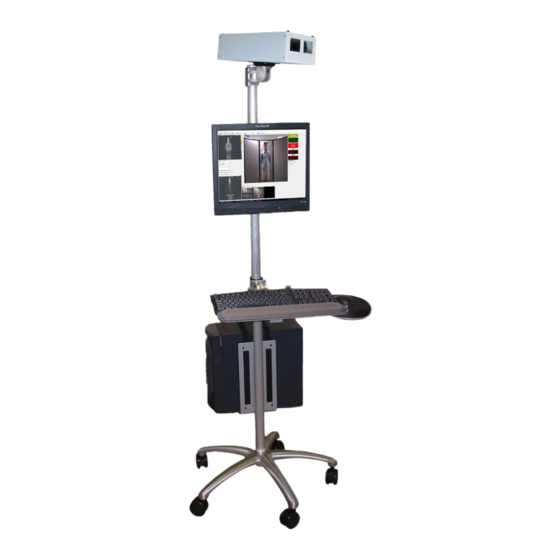
1.5 Thermoscreen Accessories Mobile Computer Stand The Mobile Computer Stand (see figure 1.5.1) provides a convenient way to operate, transport, and store the Thermoscreen System and allows the fever screening station to be easily moved to alternate locations to screen additional areas or to accommodate changes in pedestrian traffic. - Page 21 Portable Screening Wall The Portable Screening Wall (see figure 1.5.2) can be placed behind the Screening Zone to prevent reflective or hot background objects from affecting Screening Measurements. This foldout wall is comprised of three acoustical panels that are connected with 360-degree hinges. Each panel is wrapped with acoustical flame retardant fabric and secured by an aluminum frame.
-
Page 22: Spring Singapore Requirements
1.6 Spring Singapore Requirements SPRING Singapore, a national standards and accreditation organization, developed and published the following technical references: Thermal imagers for human temperature screening Part1: Requirements and test methods (TR 15: Part 1: 2003 ISBN 9971-67-963-9) Thermal imagers for human temperature screening Part 2: Implementation guidelines (TR 15: ... -
Page 23: Site Setup
2 Site Setup 2.1 Site Conditions The preparation of the fever Screening Area requires careful consideration. Incorrect site selection can affect the accuracy of Screening Measurements. Thermoscreen measures the Facial Skin Temperature of subjects, which is not only dependent on Internal Core Temperature but also on many factors including ambient air temperature and humidity. - Page 24 Screening Zone Background The area within the field-of-view of the camera must be free of hot or reflective objects. Except for the subject to be screened, there must be no other persons in the scene. Use the portable screening wall to block unwanted objects or people in the background (see section 3.5 Portable Screening Wall).
-
Page 25: Site Design
Screening Zone. Thermoscreen IS640 Thermoscreen IS640 Radiometric Infrared Cameras are equipped with a manually focusable lens providing a 52° HFOV. This wide field-of-view is useful when space is limited, and subjects must be screened at close distances. This lens is shipped pre-focused at 200cm (6’... -
Page 26: Operator Training
Manual Screening Mode Protocol This screening mode can be subdivided into two categories: individual and continuous screening. Individual Screening Individual screening requires each subject to stand still at a fixed distance from the camera while being screened. This screening method is employed in situations that require more detailed and careful screening and when stopping subjects briefly does not cause problems. - Page 27 2.4 Example: Manual Screening (Individual) A Thermoscreen System is placed at the entrance of a school to screen students and visitors upon entering the building (see figure 2.4.1). When operating in Manual Screening Mode and requiring each individual to stop briefly to be screened, a single Thermoscreen station can effectively screen up to 1,200 subjects per hour.
- Page 28 “Please remove “Exit only” sign eyeglasses” sign Stanchions Portable Screening Wall Screening Line Mat “Please stand still Door and look at the Operator 2 camera” sign Nurse Station Camera field Thermoscreen of view System Operator 1 Drawing not to scale Figure 2.4.1 –...
- Page 29 2.5 Example: Manual Screening (Continuous) A Thermoscreen System is placed at an airport terminal gate to screen arriving passengers (see figure 2.5.1). When operating in Manual Screening Mode and screening multiple subjects simultaneously as they walk through the Screening Zone, a single Thermoscreen station can effectively screen over 5,000 subjects per hour.
- Page 30 Arriving Passengers “Please remove eyeglasses” sign Jetway “Please look at the camera” sign Stanchions Operator 2 Camera field of view Nurse Station Thermoscreen System Operator 1 Drawing not to scale Figure 2.5.1 – Manual Screening Mode: Continuous operation at airport terminal gate Page 29 of 145 Thermoscreen User Manual 2020-03-09...
- Page 31 2.6 Example: Automated Screening (Single) A Thermoscreen System is placed at the entrance of a hospital to screen patients and visitors upon entering the building (see figure 2.6.1). When operating in Automated Screening Mode that requires each individual to stop briefly to be screened, a single Thermoscreen station can effectively screen up to 1,200 subjects per hour.
- Page 32 “Please remove eye glasses” sign “Exit only” sign Stanchions Portable Screening Wall Screening line mat “Please stand still Door and look at the Operator 2 camera” sign Nurse Station Camera field Thermoscreen of view System Operator 1 Drawing not to scale Figure 2.6.1 –...
-
Page 33: Automated Screening (Multiple)
2.7 Example: Automated Screening (Multiple) Two Thermoscreen Systems are placed at the entrance of an office building lobby to screen employees and visitors upon entering the building (see figure 2.7.1). When operating in Automated Screening Mode that requires each individual to stop briefly to be screened, a single Thermoscreen station can effectively screen up to 1,200 subjects per hour. - Page 34 “Exit only” sign Door “Please remove eyeglasses” Stanchions sign Portable “Please stand still and Screening Wall look at the camera” sign Screening Line Mat Camera field Operator 3 of view Nurse Station Thermoscreen Thermoscreen System #1 System #2 Operator 1 Operator 2 Drawing not to scale Figure 2.7.1 –...
-
Page 35: Automated Screening (Self)
2.8 Example: Automated Screening (Self) A Thermoscreen System is placed at the entrance of an office building to screen employees and visitors upon entering the building (see figure 2.8.1). When operating in Automated Screening Mode that requires each individual to stop briefly to be screened, a single Thermoscreen station can effectively screen up to 1,200 subjects per hour. - Page 36 “Please remove “Exit only” sign eyeglasses” sign Stanchions Portable Screening Wall Screening Line Mat “Please stand still Door and look at the camera” sign Nurse Station Camera field Thermoscreen of view System Drawing not to scale Figure 2.8.1 – Automated Screening Mode: Self operation at office building entrance Page 35 of 145 Thermoscreen User Manual 2020-03-09...
-
Page 37: Hardware Setup
3 Hardware Setup 3.1 Unpacking Caution: The Thermoscreen Infrared Camera is a delicate precision instrument and should be handled with care. The camera is shipped preinstalled in the Camera Enclosure. The enclosure helps protect the camera from minor bumps and scratches. The enclosure will not protect the camera from damage from dropping or severe physical abuse. - Page 38 Portable Screening Wall Ceiling/pedestal mount bracket Wall mount bracket Missing Components If any items are missing, please contact Optotherm’s Technical Support Department at: Phone: +1 (724) 940-7600 Fax: +1 (724) 940-7611 Email: support@optotherm.com Page 37 of 145...
-
Page 39: Mounting The Camera Enclosure
3.2 Mounting the Camera Enclosure Note: If you purchased the Mobile Computer Stand optional accessory, please see section 3.4 of this manual for instructions on how to mount the Camera Enclosure to the stand. The Camera Enclosure can be mounted to the pedestal/ceiling or wall bracket. First, attach the mounting bracket to the bottom of the Camera Enclosure using the four M3 x 8mm screws and 2mm hex driver provided. - Page 40 Camera field of view Figure 3.2.2 – Screening subjects as they face the camera Page 39 of 145 Thermoscreen User Manual 2020-03-09...
-
Page 41: Connecting And Testing The Camera
3.3 Connecting and Testing the Camera Note: If you purchased the Mobile Computer Stand, please see section 3.4 of this manual for instructions on connecting the camera cables to the stand. Caution Before touching the camera, camera cables, or computer cables, ground yourself using a grounding strap or by touching a grounded object, such as the chassis of a computer that is plugged in. -
Page 42: Mobile Computer Stand
3.4 Mobile Computer Stand Follow the instructions in this section if you purchased the Mobile Computer Stand. This section contains instructions to assemble the stand and to install the Thermoscreen components on the stand. All of the hardware required for assembly and installation is included. Spring Nuts Spring nuts are used to attached accessories to the Mobile Computer Stand pole. - Page 43 Insert seven (7) M6 spring nuts into the same pole slot with the threads facing out (see figure 3.4.3). Slide the spring nuts down using the hex wrench. Push the pole cap onto the top of the pole (see figure 3.4.4).
- Page 44 Connecting the Computer Bracket Using a hex wrench, slide the two lowest spring nuts down near the bottom of the pole (see figure 3.4.8). Attach the computer bracket to the pole approximately 10 cm (4”) from the bottom of the pole by screwing the two M6 x 8mm countersink screws (see figure 3.4.9) into the two spring nuts using the 4mm hex wrench provided (see figure 3.4.10).
- Page 45 Installing the Keyboard Support Slide the keyboard support over the top of the pole and position it approximately 36” above the floor (see figure 3.4.11). Slide the second lowest unused spring nut into position. Important: Position the lowest unused spring nut between the computer bracket and the keyboard support for mounting the grounding cable in a later step.
- Page 46 Installing the Mouse Pad Platform Slide the mouse pad arm through the holes in the bottom of the keyboard support (see figure 3.4.15). Slide the mouse pad platform onto the rails of the mouse pad arm and position the platform near the ends of the rails (see figure 3.4.16).
- Page 47 Installing the Speaker Support Insert the support knob threads through the black plastic stop (see figure 3.4.20). Screw the knob into the lowest unused spring nut approximately 15 cm (6”) above the top of the monitor support (see figure 3.4.21). Figure 3.4.20 –...
- Page 48 Installing the Camera Support Insert the support knob threads through the black plastic stop (see figure 3.4.22). Screw the knob into the unused spring nut at the top of the pole and tighten approximately 8 cm (3”) from the top of the pole (see figure 3.4.23).
- Page 49 Mounting the Keyboard Loosen the hand rest thumbscrews and fully extend the hand rest (see figure 3.4.27). Position the keyboard on the keyboard support so that the top edge of the keyboard is seated against both foam pads. Push the hand rest tight against the keyboard and tighten the hand rest thumbscrews (see figure 3.4.28).
- Page 50 Mounting the Monitor Carefully place the monitor face down on a flat, clean surface. Caution: Take care not to scratch or damage the monitor screen during this operation. Unscrew the four screws from the back of the monitor (see figure 3.4.29) and set them aside. If a monitor mounting plate (see figure 3.4.30) is included with your system, install the plate (4.53”...
- Page 51 Mounting the Monitor Sound Bar The sound bar clips into the bottom of the speaker support. Note: The speaker support can be rotated around the pole to project sound to either the operator or to the subject being screened. Mounting the Camera Enclosure Carefully remove the Camera Enclosure from the black plastic carrying case and place the enclosure upside down on a level surface.
- Page 52 Power Cord Organizer Bag The power cord organizer bag is used to neatly stow the computer and monitor power cords and surge- protected power strip. Hang the power cord organizer bag around the pole just above the computer (see figure 3.4.38) and place the power strip in the bottom of the bag. Feed the power strip cord out through the top opening of the bag.
- Page 53 Connecting the Computer Cables Caution: Before touching the computer cables, ground yourself using a grounding strap or by touching a grounded object, such as the chassis of a computer that is plugged in. Connect the monitor power cord and video cable to the monitor. Bundle together the monitor power, video, and audio cords using the 3”...
- Page 54 Connecting the Camera Cables Caution: Before touching the camera, camera cables, or computer cables, ground yourself using a grounding strap or by touching a grounded object, such as the chassis of a computer that is plugged in. Bundle together the Camera Link cable and the GigE Visual Camera cable and secure them to the pole approximately 8”...
- Page 55 Grounding the Stand Using the 3/16” hex driver, insert the M6 x 8mm hex bolt through the grounding wire ring terminal and washer and screw into the unused spring nut above the computer bracket (see Figure 3.4.43). Feed the grounding cable in through the top opening of the cord organizer bag and plug it into the power strip. Figure 3.4.43 –...
-
Page 56: Portable Screening Wall
3.5 Portable Screening Wall Unfold the Portable Screening Wall and place it directly behind the Screening Line Mat to prevent hot or reflective background objects from affecting Screening Measurements. Instruct subjects to walk from one side of the screening wall onto the Screening Line Mat, turn and face the camera, and then exit on the other side of the screening wall. -
Page 57: Lens Focusing
3.6 Lens Focusing Caution: Before touching the camera, ground yourself using a grounding strap or by touching a grounded object, such as the chassis of a computer that is plugged in. Removing the Camera Enclosure Top Panel To access the Infrared Camera lens for focusing, Remove the four thumbscrews on the top of the Camera Enclosure (see figure 3.6.1) and remove the top panel of the enclosure. - Page 58 Focusing the Visual Camera Thermoscreen Visual Cameras are shipped with their lenses pre-focused at a 2m Screening Distance. There are three different adjustable rings on the Visual Camera (see figure 3.6.3). Important: The zoom ring is preset at the factory for proper zoom level to match the Infrared Camera and should not be changed.
-
Page 59: Computer Setup
4 Computer Setup 4.1 Overview IMPORTANT: READ THIS FIRST IF YOU PURCHASED THE COMPUTER FROM OPTOTHERM, ALL OF THE HARDWARE AND SOFTWARE HAS BEEN PRE-INSTALLED ON THE COMPUTER. THEREFORE, YOU SHOULD NOT PERFORM THE PROCEDURES IN SECTION 4: COMPUTER SETUP. - Page 60 How to Determine Which .NET Version is Installed on Your Computer If you have upgraded .NET, the upgrade will be listed in the Programs and Features window. If you have not upgraded .NET, you will need to use the following procedure to determine your .NET version. 1.
- Page 61 Therefore, you should not perform the procedures in this section. If you did NOT purchase the computer from Optotherm, you need to perform the following steps to install the computer hardware and software. Note: These steps must be performed in the order listed.
-
Page 62: Camera Link Board Installation
4.2 Camera Link Board Installation Important: If you purchased the computer from Optotherm, all of the hardware and software has been preinstalled on the computer. Therefore, you should not perform the procedures in this section. The Camera Link board is a circuit board with PCIe x1 connector that must be installed in one of the available PCIe slots of your computer. -
Page 63: Gige Board Installation
4.3 GigE Board Installation Important: If you purchased the computer from Optotherm, all of the hardware and software has been preinstalled on the computer. Therefore, you should not perform the procedures in this section. The GigE board is a circuit board with PCIe x4 connector that must be installed in one of the available PCIe slots of your computer. - Page 64 Board Device Driver Installation 1. Close any applications that may be running. 2. Insert the Thermalyze USB flash drive. Note: If a “Setup” or Windows “AutoPlay” window opens automatically, close the window. 3. Open the folder named [Realtek] Windows Gigabit Network Adapter ver…, open the folder whose name describes your operating system, right-click on setup.exe and select Run as Administrator.
-
Page 65: Matrox Installation
4.4 Matrox Installation Important: If you purchased the computer from Optotherm, all of the hardware and software has been preinstalled on the computer. Therefore, you should not perform the procedures in this section. Thermalyze utilizes the Matrox image processing library to perform complex processing on thermal images. - Page 66 4. In the bottom right corner of the window click the Generate button. 5. Copy the text in the Lock Code box. 6. Email the Lock Code code to support@optotherm.com. An Optotherm support engineer will generate a License Code and send it to you in a reply to your email.
-
Page 67: Ni-Ui Installation
4.5 NI UI Installation Important: If you purchased the computer from Optotherm, all of the hardware and software has been preinstalled on the computer. Therefore, you should not perform the procedures in this section. Thermalyze utilizes National Instruments libraries for user interface controls. -
Page 68: Thermalyze Software Installation
4.6 Thermalyze Installation Important: If you purchased the computer from Optotherm, all of the hardware and software has been preinstalled on the computer. Therefore, you should not perform the procedures in this section. Thermalyze Software Installation 1. Close any applications that may be running. -
Page 69: Calibration Data Installation
C:\Program Files\Optotherm\Thermalyze\Calibration Calibration Data Changes If you receive changes to your camera’s calibration data from Optotherm, you will need to install the new calibration data on your computer according the following instructions: 1. Close any applications that may be running. -
Page 70: Key Concepts
5 Key Concepts 5.1 Skin Offset Facial Skin Temperature - Internal Core Temperature Correlation Studies have shown that there is a correlation between Internal Core Temperature and Facial Skin Temperature. The maximum temperature measured between the eyes usually provides the best correlation with Internal Core Temperature for the following reasons: 1. - Page 71 Manual Screening Mode When screening subjects in this mode, Skin Offset can be calculated using the Measure Skin Temperature Offset window (see figure 7.6.1). During this procedure, both Thermoscreen and Medical Thermometer measurements are conducted on a number of test subjects. Skin Offset is determined by calculating the average difference between the Medical Thermometer and Thermoscreen measurements.
-
Page 72: Fever Threshold
5.2 Fever Threshold Internal Core Threshold is the threshold, often 38°C (100.4°F), used by medical practitioners to indicate a fever when using a Medical Thermometer. However, studies indicate that the threshold for a fever can vary depending on a number of factors such as age, gender, time of day, activity level, and clothing. For this reason, the threshold for a fever should be determined based on the characteristic of specific subject groups. - Page 73 The value of Fever Threshold depends on the specific requirements of your particular fever screening operation. For example, many hospitals are able to conduct more thorough fever screening evaluations because they have sufficient personnel available to handle large numbers of False Violations. Hospitals, therefore, would typically set Fever Threshold lower in order to minimize Missed Detections.
-
Page 74: Measuring Internal Core Temperature
5.3 Measuring Internal Core Temperature Internal Core Temperature can be measured using one of the following Medical Thermometers: Electronic or conventional glass mercury thermometers for oral, axilla (under arm), and rectal measurements Tympanic (ear) thermometers Studies demonstrate that the range of normal Internal Core Temperature is much wider than is generally understood. -
Page 75: Thermalyze Software
6 Thermalyze Software 6.1 Overview Thermalyze fever screening software (see figure 6.1.1) runs on the Thermoscreen computer and processes and displays Thermal Images captured from the Thermoscreen Infrared Camera. The following sections in this chapter describe all software controls and settings. Figure 6.1.1 –... - Page 76 We strive to correct program errors and provide bug fixes as soon as possible and we greatly appreciate your efforts to provide us with relevant information. Please send error information to: support@optotherm.com. Page 75 of 145 Thermoscreen User Manual 2020-03-09...
-
Page 77: File Menu
The size of the exported image is proportional to the size of the displayed image. Exported images are saved in the Optotherm\Thermalyze\Export folder unless you specify a different folder. T he default file name is created using the date and time the image was captured. -
Page 78: Setup Menu
Note: When Thermalyze is closed down, the values of all user-changeable parameters are saved to a file name Thermalyze.ini in the Optotherm\Thermalyze folder. When Thermalyze is restarted, the saved settings are retrieved from the file and then loaded into Thermalyze. In other words, Thermalyze starts with the same settings values as when it was last closed down. -
Page 79: User Preferences
6.3.2 User Preferences The User Preferences window (see figure 6.3.2.1) contains global software settings that control how Thermalyze operates and displays data. Open this window by selecting the User Preferences item from the Setup menu. Figure 6.3.2.1 – User Preferences window Display Units Choose the units in which temperature and length will be displayed. - Page 80 Flip Captured Images These controls are used to view Thermal Images in the proper orientation determined by the viewing direction of the operator in relation to the subjects to be screened. The Vertically box is usually unchecked unless the camera is mounted upside down. For typical screening setups where the operator is located behind the screen (relative to the subjects to be screened), the Horizontally box should be unchecked.
- Page 81 Performance The rate at which images can be captured and displayed by the Optotherm IS640 Infrared Camera is 60 frames per second (fps). The Image Processing Rate is displayed in the status bar in the bottom left of the Thermalyze window. Image capture rate can sometimes fall below 60 fps if multiple software tools are in use simultaneously.
-
Page 82: Messages
6.3.3 Messages The Messages window (see figure 6.3.3.1) displays important information regarding the operation of Thermalyze such as camera communication errors or programming logic errors. Open this window by selecting the Show Messages item from the Setup menu. Figure 6.3.3.1 – Messages window Display Messages Uncheck this box and close the window to prevent the Messages window from re-opening when a message occurs. -
Page 83: Bad Pixel Replacement
When your camera was calibrated at Optotherm, any bad pixels (called factory bad pixels) were identified and marked. You do not have access to, and cannot change, factory bad pixels. However, if you notice any pixels whose response is suspect, you can mark them so that they are replaced when capturing images. - Page 84 # Bad Pixels This field displays the number of bad pixels that the user has marked in the image. Show Bad Check this box to display a light blue square enclosing each bad pixel that has been Pixels marked. Note: Bad pixels cannot be displayed while capturing images. Bad Pixel Choose the color of the markers used to to display the bad pixels.
-
Page 85: Thermal Camera
6.4 Thermal Camera The buttons in the Thermal Camera section of the toolbar at the top of the Thermalyze window (see figure 6.4.1) are used to setup and control the Thermoscreen Infrared Camera. Figure 6.4.1 – Thermal Camera setup and control buttons Thermal Camera Buttons Initialize Camera Press this button to setup the Matrox Solios Camera Link video board for... -
Page 86: Fever Screening
6.5 Fever Screening The buttons in the Screening section of the toolbar at the top of the Thermalyze window (see figure 6.5.1) are used to setup and control Fever Screening operation. Figure 6.5.1 – Fever Screening setup and control buttons Fever Screening Menu and Buttons Visual Camera Press this button to display the Visual Camera window. -
Page 87: Visual Image
6.5.1 Visual Image The Visual Camera window displays live visual images to help operators identify subjects as they are screened. Display this window by pressing the Visual Camera button in the Screening section of the toolbar at the top of the Thermalyze window. Figure 6.5.1.1 –... - Page 88 Camera Protocol Select the communication protocol of the camera; GigE Vision or USB3 Vision. GigE should be selected for the Thermoscreen Visual Camera Note: Both protocols adhere to the GenICam standard. Tip: If the GigE port in which the camera is plugged into is changed while Thermalyze is running, you may need to select GigE from the drop-down list for the camera to recognized.
-
Page 89: Screening Violations
6.5.2 Screening Violations The Screening Violations window (see figure 6.5.2.1) displays Violation Images: Thermal and Visual Images that were captured during the previous three Fever Threshold Violations. Display this window by pressing the Violation Review button in the Screening section of the toolbar at the top of the Thermalyze window. -
Page 90: Violation Review
6.5.3 Violation Review The Violation Review window (see figure 6.5.3.1) displays the Violation Image and Violation Sequence that was selected in the Screening Violations window. Display this window by pressing the Violation Review button in the Screening section of the toolbar at the top of the Thermalyze window. A Violation Image and Sequence is reviewed in order to identify the subject and to confirm that the Fever Threshold Violation occurred on a subject face and not on hair or clothing. - Page 91 The default file format is png, which has the advantage of compression but no image quality loss. Reports are saved in the Optotherm\Thermalyze\Export\Violations folder unless you specify a different folder. T he default file name is created using the date and time the violation occurred and files are saved in a day folder that is contained within a year month folder.
- Page 92 Violation Sequence Controls The individual images within a Violation Sequence can be displayed using the multimedia controls below or by dragging the trackbar. This currently displayed image number is displayed to the right of the trackbar. First Image Click this button to display the first image in the Violation Sequence. Back One Image Click this button to display the previous image in the Violation Sequence.
-
Page 93: Screening History
Each Screening Measurement and Result is automatically appended to a file named ScreeningHistory YYYY MM that is located in the directory named Optotherm\Thermalyze\Screening History. YYYY MM indicates the year and month in which the Screening Measurements were conducted. For example, the file named ScreeningHistory 2015 04.txt contains all of the... - Page 94 The size of the exported image is proportional to the size of the Screening History window. Exported windows are saved in the Optotherm\Thermalyze\Export folder unless you specify a different folder. Print Print the Screening History window.
- Page 95 Zoom Buttons Select Select this button when finished zooming or panning to allow placement of the vertical cursor on the plot. Zoom In Select this tool and then click and drag on the plot to select the area of interest on the plot to zoom into.
- Page 96 Cursor Buttons The vertical cursor line is used to select an individual screening measurement and display its associated data. Note: If there are many Screening Measurements displayed on the plot, there may be multiple measurements represented by each horizontal pixel location. Use the Move Cursor buttons to step through individual Screening Measurements.
- Page 97 Screening Period to Plot Select the date/time range of screening measurements to plot. Note: The date/time range of the currently plotted Screening Measurements is displayed at the bottom of the Screening History window. From Enter the start date/time to define the range of screenings to plot. Note: The minimum and maximum dates that can be selected are determined by the minimum and maximum dates in the history file that is currently open.
- Page 98 Screening Range Statistics These fields display statistics associated with the currently plotted screening measurements. # Tests This field displays the number of screening measurements. Passes This field displays the number of passing Screening Results. Fails This field displays the number of failing Screening Results. Body Core These fields display the mean and standard deviation of the Internal Core Estimate.
-
Page 99: Height Scale
6.5.5 Height Scale The Height Scale (see figure 6.5.5.1) is a measurement scale that can be displayed on the Thermal Image to help position and aim the Infrared Camera for screening a range of subject heights. Display this scale by pressing the Show Height Scale button in the Screening section of the toolbar at the top of the Thermalyze window. -
Page 100: Fever Screening Setup
6.5.6 Fever Screening Setup The Fever Screening Setup window (see figure 6.5.6.1) contains settings for configuring the Screening Process. Display this window by pressing the Fever Screening Setup button in the Screening section of the toolbar at the top of the Thermalyze window. Figure 6.5.6.1 –... - Page 101 Person Detection Before a subject can be screened, the subject must first be detected within the Screening Zone. Detection A subject is detected when at least one image pixel has temperature above the Temperature Detection Temperature setting. When this box is checked, Detection Temperature is automatically calculated by Auto Detect measuring the background temperature of the Screening...
- Page 102 Measure Skin Offset Click this button on the Fever Screening Setup window to display the Measure Skin Offset window (see figure 6.5.6.2). When operating in Automated Screening Mode with the Automatic Skin Offset: Enable box checked, Skin Offset is automatically calculated as subjects are screened. However, when operating in Manual Screening Mode (or Automated Screening Mode with the Automatic Skin Offset: Enable box unchecked), the Skin Offset must be calculated using a Medical Thermometer and Thermoscreen measurements.
- Page 103 Detection Temperature. Reports are saved in png format, which has the advantage of compression but no image quality loss. Reports are saved in the Optotherm\Thermalyze\Export\Violations folder. he report file name is created using the date and time the violation occurred and files are saved in a day folder that is contained within a year month folder.
- Page 104 Automatic Skin Enter the number of previous Screening Measurements to use when Offset: Sample calculating Skin Offset. A new value is calculated when the number of Size Screening Measurements equals or exceeds Sample Size within the previous two-hour period. Screening measurements conducted more than two hours earlier are disregarded.
-
Page 105: Screening Results
6.5.7 Screening Results The Screening Results window (see figure 6.4.7.1) displays the results of screening tests and also contains screening settings that may often need to be adjusted by operators. Note: The PASS indicator is not displayed in Manual Screening Mode. Figure 6.5.7.1 –Screening Results window Page 104 of 145 Thermoscreen User Manual 2020-03-09... - Page 106 Screening Results PERSON This indicator light illuminates when a subject is detected in the Screening Zone. PASS This indicator light illuminates when a subject passes the Screening Test. FAIL This indicator light illuminates when a subject fails the Screening Test. Current This field displays the most recent Internal Core Estimate.
-
Page 107: Regions
6.6 Regions Ideally, there should be no heat sources or reflective objects within the camera’s field of view. When such objects cannot be removed or blocked, regions allow you to exclude areas so that they don't interfere with the Screening Process. Regions are geometrical figures drawn on the screen that enclose groups of pixels (see figure 6.6.1). - Page 108 Click this button to display the Open Regions dialog. Save Regions Regions are saved in Click this button to display the Save Regions dialog. the Optotherm\Thermalyze\Regions folder unless you specify a different folder. Select Select this tool to resize and reposition regions.
- Page 109 Startup Region When Thermalyze is started, the program searches the Optotherm\Thermalyze\Regions folder for the file Startup.orgn. If this file is located, it is opened, and its regions are displayed. Create your own custom set of startup regions and save over this file so that they open upon program startup.
-
Page 110: Software Setup And Operation
7 Software Setup and Operation 7.1 Capturing Thermal Images Important: When the camera is first powered, or if the system has been moved to another location having a different ambient temperature (as described in section 2.1 of this manual), it is necessary to allow the camera to stabilize in temperature for at least 10 minutes prior to operation in order to obtain accurate Screening Measurements. - Page 111 This field displays the current temperature of the main microprocessor in the Temp Infrared Camera. Note: This parameter is displayed so that it can be provided to Optotherm technical support if requested. Page 110 of 145 Thermoscreen User Manual 2020-03-09...
-
Page 112: Capturing Visual Images
7.2 Capturing Visual Images To display the Visual Camera window, press the Visual Camera button in the Screening section of the top toolbar (see figure 7.2.1). To begin capturing and displaying Visual Images, press the Capture Visual Images button at the top of the Visual Camera window. If there are any problems capturing images, make sure the GigE cable is securely connected between the computer and Visual Camera. -
Page 113: Aiming The Camera
7.3 Aiming the Camera The Height Scale is a vertical measurement scale that can be displayed in the Thermal Image to help operators position and aim the camera so that subjects with various heights can be screened effectively. To aim the camera using the Height Scale, follow these steps: 1. -
Page 114: Excluding Background Objects
7.4 Excluding Background Objects In most cases, there should be no heat sources or reflective objects within the camera’s field of view. When such objects cannot be removed or blocked, regions allow you to exclude areas so that they don't interfere with the Screening Process. -
Page 115: Person Detection
7.5 Person Detection Note: Person Detection settings are available in the Fever Screening Setup window. The detection of a subject begins the Screening Process. This condition is met when a temperature equal to or above Person Detection Temperature is detected within the Screening Zone. -
Page 116: Measuring Skin Offset
7.6 Measuring Skin Offset When operating in Automated Screening Mode with the Automatic Skin Offset: Enable box checked, Skin Offset is automatically calculated as subjects are screened. However, when operating in Manual Screening Mode (or Automated Screening Mode with the Automatic Skin Offset: Enable box unchecked), effective fever screening requires accurate measurement of Skin Offset using a Medical Thermometer and the Measure Skin Temperature Offset window (see figure 7.6.1). -
Page 117: Adjusting Skin Offset
Measuring Skin Offset Calculate Skin Offset according to the following procedure: 1. Open the Measure Skin Temperature Offset window by clicking the Measure Skin Offset button in the Fever Screening Setup window. 2. Click the Clear All Rows button to delete any existing data. 3. -
Page 118: Adjusting Fever Threshold
7.8 Adjusting Fever Threshold Fever Threshold regulates the number of Missed Detections and False Violations. In many fever screening applications, Fever Threshold may not need to be changed. Operators can periodically adjust this setting however, to regulate the number of Missed Detections and False Violations (see section 5.2 Fever Threshold). -
Page 119: Fever Threshold Violations
7.9 Fever Threshold Violations A Fever Threshold Violation occurs when a subject’s Internal Core Estimate exceeds Fever Threshold. Screening Violations Window The Screening Violations window (see figure 7.9.1) displays Violation Images: Thermal and Visual Images that were captured during the previous three Fever Threshold Violations. Display this window by pressing the Violation Review button in the Screening section of the toolbar at the top of the Thermalyze window. - Page 120 Violation Review Window The Violation Review window (see figure 7.9.2) displays the Violation Image and Violation Sequence that was selected in the Screening Violations window. Display this window by pressing the Violation Review in the Screening section of the toolbar at the top of the Thermalyze window. The date and button time the violation occurred is displayed above the image.
- Page 121 Fever Threshold Violation (Manual Screening Mode) This section describes the events that occur during a Fever Threshold Violation when operating in Manual Screening Mode. Many of these events however, also occur when operating in Automated Screening Mode. See section 7.10 Automated Screening Mode for events specific to operating in Automated Screening Mode.
- Page 122 Violation Image files are saved in a day folder that is contained within a year month folder that is located in the Images directory. For example, the Violation Image file Optotherm\Thermalyze\Images\2020 8\24\085427.oimg was saved on August 24, 2020 at 8:54:27 am. Violation Sequences and exported images are similarly saved in the Sequences and Export directories.
- Page 123 Fever Threshold Violation Confirmation When a Fever Threshold Violation occurs, the operator should examine the most recent Violation Image in the left of the Violation Review window to verify that the violation occurred on the subject’s face, and not on hair, clothing, or on an object in the background. Observe where the colored pixels are located. If they are located on the subject’s face, the operator can be confident that a valid Fever Threshold Violation has occurred.
-
Page 124: Automated Screening Mode
7.10 Automated Screening Mode To activate Automated Screening Mode, check the Automated Screening box in the Fever Screening Setup window. This mode of screening provides the following features and advantages over Manual Screening Mode: Face detection Movement detection Audible verbal commands ... - Page 125 Automated Screening Mode Process 1. When at least one pixel with Person Detection Temperature has been detected within the Screening Zone, the PERSON indicator illuminates, and the subject is instructed to "please stand still and look directly at the camera.” Thermalyze examines the number and shape of the pixels with temperature above Person Detection Temperature to determine if the subject’s face is in view.
- Page 126 Face Detection Brackets Colored brackets are displayed around those pixels whose temperature exceeds Person Detection Temperature (see figure 7.10.1). A status message is also displayed above the brackets. Figure 7.10.1 – Face detection brackets Page 125 of 145 Thermoscreen User Manual 2020-03-09...
- Page 127 The status message and the color of the brackets indicates the status of the Screening Process and can be helpful when determining the reason for any problems when setting up fever screening parameters. Screening Process status messages are also displayed at the bottom of the Screening Results window. Bracket Message Description...
- Page 128 Automatic Skin Offset In Automated Screening Mode, Skin Offset can be automatically updated to compensate for changes in ambient temperature and for variations in the Internal Core Temperature due to Circadian Cycle effects. Because a number of Screening Measurements must be conducted before Skin Offset can be re- calculated, when screening the first subjects, the value of Skin Offset is the value used during the previous screen.
- Page 129 1. Create a sound file approximately four seconds long instructing subjects prior to being screened to “Please stand still and look directly at the camera.” Name the new sound file Stand Still Custom.wav and place it in the Program Files\Optotherm\Thermalyze\Sounds folder. 2. Create a sound file approximately three seconds long instructing subjects whose Screening Result = Pass to “Thank you, you may proceed.”...
-
Page 130: Maintenance
8 Maintenance 8.1 Cleaning the Lens The Lens Care Kit is provided with your system and includes the following components. Air bulb blower Lens cleaning solution Wiping cloth Cotton swabs Precautions To protect the lens from damage, follow these guidelines. Never touch the lens with hard or abrasive objects. -
Page 131: Cleaning And Disinfection
8.2 Cleaning and Disinfection Important Concepts Cleaning Cleaning removes germs, dirt, and impurities from surfaces or objects. Cleaning works by using soap (or detergent) and water to physically remove germs from surfaces. This procedure does not necessarily kill germs, but by removing them, it lowers their numbers and the risk of spreading infection. Disinfecting Disinfecting kills germs on surfaces or objects. -
Page 132: Appendix
9 Appendix 9.1 Quick Start Instructions The following steps describe the program setup procedures for operating in both Automated and Manual Screening Mode. Capture Thermal Images 1. Start the Thermalyze fever screening software. 2. Press the Visual Camera button to display the Visual Camera window. 3. - Page 133 Setup for Automated Screening Mode 1. Open the Fever Screening Setup window. 2. Check the Auto Detect and Automated Screening: Enable boxes. 3. Check the Automated Messages: Enable box, check the Automatic Skin Offset: Enable box, and set Automatic Skin Offset: Sample Size to 10. 4.
-
Page 134: Troubleshooting
9.2 Troubleshooting Camera Communication Problems Symptom: When starting camera communication, a window opens and displays the following message: Camera communication could not be started. Or after camera communication has been established, a window opens and displays the following message: Camera communication has stopped due to an unknown event. - Page 135 Visual Camera Image Stutter Symptom: The display of visual camera images periodically stutters. Solution 1. Open Windows Device Manager 2. Expand the Network adapters section 3. Right-click Realtek PCIe GBE Family Controller and click Properties 4. When the properties window opens, select the Advanced tab 5.
- Page 136 To obtain accurate Internal Core Temperature measurements when performing the procedure to calculate Skin Offset (see section 7.5 Measuring Skin Offset) or when confirming a fever, Optotherm recommends using an oral thermometer (see section 5.3 Measuring Internal Core Temperature). The accuracy of oral thermometer measurements, however, can be affected by several factors.
- Page 137 The Temperatures in the Current and Previous Fields Do Not Correspond The Current field displays a real-time calculation of Internal Core Estimate and is updated continuously while a subject is being screened. In Manual Screening Mode, the Previous field is updated only when a Fever Threshold Violation occurs.
- Page 138 Regions or Face Detection Brackets are Misaligned on the Visual Image Make sure the Flip Image Horizontally box in the Video Settings window is set to the same value as the Flip Captured Images Horizontally box in the User Preferences window (see section 6.3.2 User Preferences).
- Page 139 We strive to correct program errors and provide bug fixes as soon as possible and we greatly appreciate your efforts to provide us with relevant information. Please send error information to: support@optotherm.com. Page 138 of 145...
-
Page 140: Technical Support
9.3 Technical Support Service Policy Optotherm is committed to providing fast and efficient technical support should you experience any difficulties installing or operating your system. Please contact the Optotherm Technical Support Department and our engineers will be happy to assist you. -
Page 141: Thermoscreen System Specifications
9.4 Thermoscreen System Specifications IS640 Detector Infrared Detector Uncooled amorphous silicon microbolometer Array Size 640 x 480 pixels Detector Pitch 17 µm Spectral Response 7-14 µm Thermal Time Constant < 11 ms Thermographic Data Frame Rate 60 Hz Video Output Format Camera Link Time to First Image <... - Page 142 IS640 with Macroscopic Lens Optics Pixel Resolution 140 μm resolution minimum (at 100 mm) Focus Manual Working Distance 100 mm to infinity Field of View 89.6 x 67.2 mm minimum Focal Length 12 mm Working F/# 1.02 Measurement Calibration Range* 10 to 60°C Sensitivity (NETD)†...
-
Page 143: Infrared Camera Calibration
Camera Calibration Checks We recommend yearly calibration checks to assure that your thermal imaging camera is operating optimally and within its specified accuracy. Calibration checks should be performed at Optotherm where traceable calibration equipment is used, and proper procedures are followed. -
Page 144: Software Warranty
Limited Warranty Optotherm, Inc. warrants this software package to be free from defects in material and workmanship for a period of one year from the date of original purchase. Optotherm, Inc. assumes no responsibility for any special or consequential damages. -
Page 145: Hardware Warranty
Optotherm. If you discover a defect, Optotherm will, at its option, repair or replace the product at no charge provided you return it during the warranty period, with transportation charges prepaid, to the Optotherm Technical Support Department.
Need help?
Do you have a question about the Thermoscreen IS640 and is the answer not in the manual?
Questions and answers