Advertisement
Quick Links
Electro Optical Components, Inc.
5464 Skylane Boulevard, Suite D, Santa Rosa, CA 95403
Toll Free: 855-EOC-6300
www.eoc-inc.com
|
info@eoc-inc.com
The universal amplifier
for photodiodes
with built-in cooler
AMT-07M
Operations manual
IBSG Co., Ltd., 26 Polytechnicheskaya str., St-Petersburg, 194021 RUSSIA, ns@iropt6.ioffe.ru, www.ibsg-st-petersburg.com
Advertisement

Summary of Contents for IBSG AMT-07M
- Page 1 Electro Optical Components, Inc. 5464 Skylane Boulevard, Suite D, Santa Rosa, CA 95403 Toll Free: 855-EOC-6300 www.eoc-inc.com info@eoc-inc.com The universal amplifier for photodiodes with built-in cooler AMT-07M Operations manual IBSG Co., Ltd., 26 Polytechnicheskaya str., St-Petersburg, 194021 RUSSIA, ns@iropt6.ioffe.ru, www.ibsg-st-petersburg.com...
-
Page 2: Table Of Contents
Contents 1. Application 2. Features 3. Service conditions 4. Appearance of the amplifier and its interface 5. Operating instruction 6. Technical characteristics 7. Block diagram - 2 -... -
Page 3: Application
1. Application. The amplifier AMT-07M is designed for signal extraction and detection from IR-photodiode with built-in cooler manufactured by IBSG. 2. Features. • The possibility of discrete changing of current amplification to raise the measurement accuracy. • The presence of analog output for external device connection and LCD- display for signal level indication. -
Page 4: Service Conditions
3. Service conditions. Temperature tolerance -15 °С..+15 °С Relative air humidity (at temperature + 35°С) less then 80 % Atmospheric pressure 86..107 kPa - 4 -... -
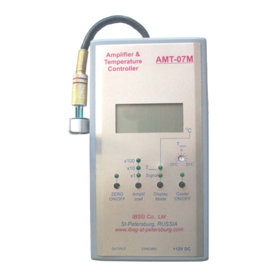
Page 5: Appearance Of The Amplifier And Its Interface
4. Appearance of the amplifier and its interface. Fig.1.Appearance of the amplifier and its interface. - 5 -... - Page 6 1. The jack for the PD connection. 2. The display for indication of the PD temperature and signal level. 3. The PD temperature adjuster. 4. The start/stop button of PD cooling. 5. The jack for the cable of AC/DC adapter. 6.
-
Page 7: Operating Instruction
Fig.3. The polarity of jackplug of cable for synchronization. Note! Without synchronization the amplifier readings can’t be true. 3. If necessary with the help of a cable connect the “Output” (7) of AMT-07M with recording instrument (for example oscilloscope or analog-to-binary converter). Figure 4. - Page 8 5. Using the button “Display mode” (8) select the PD temperature indication mode. The green LED indicator “T ” (12) will be turned on. On the LC measure display you can see (2) the real temperature of the PD’s chip. Fig.6.
- Page 9 Fig.8. The start/stop button of PD cooling with appropriate indicator. 8. Using the button “Display mode” (8) select the PD current indication mode. The green LED indicator “Signal” (9) will be turned on. Fig.9. The button of display mode selection. The LED indicator of the signal level indication mode.
- Page 10 “ZERO” mode description. The intrinsic function for background level compensation (“ZERO” mode) is used for amplification and measuring the difference between the current signal level and the signal taken for the zero level. Using the start/stop button “ZERO ON/OFF” (10) this mode can be switched. The appropriate green LED indicator will be turned and the current signal is taken for the zero level in power up time.
-
Page 11: Technical Characteristics
6. Technical characteristics. Input voltage +12 V, stabilized Voltage tolerance -5..+5 % Power consumption Less then 3 W Adjustment temperature range -15 °С..+15 °С Board dimensions 148×78×30 mm Maximal amplification 6,4×10⁶ V/А Maximal amplitude of output voltage |± 4 V| Output resistance 50 ohm Transmission band with PD24... -
Page 12: Block Diagram
6. Block diagram The block diagramme of AMT-07M is presented in fig.11. The amplifier functionally consists of the photodetector with PD, temperature sensor RT, Peltier element P and amplification-transformation circuit including preamplifier А1, bandpass amplifier ВА, variable gain amplifier A2, synchronous demodulator SD, multiplexer MX, analog-to-digital converter ADC and liquid crystal display LCD, as well as regulating-stabilizer circuit of PD temperature including amplifiers А3,... - Page 13 Fig.12. The Block diagram of AMT-07M. - 13 -...
Need help?
Do you have a question about the AMT-07M and is the answer not in the manual?
Questions and answers