Advertisement
Quick Links
SEC
1.
BASIC FUNCTIONAL DESCRIPTION
2.
INTRODUCTION
3.
UNIT CHARACTERISTICS/DIMENSIONS
4.
DIMENSIONS
5.
CONNECTIONS
6.
CONFIGURATION
7.
USE
7.1.
MAIN MENU
7.2.
CONSULTATION
7.3.
PROGRAMMING
7.4.
CHANGE CLOCK TIME
7.5.
MANUAL PROGRAMMES
7.6.
MANUAL SECTORS
7.7.
FERTILISATION TIME
7.8.
STOP
7.9.
PROGRAMME PATTERN
8.
FUNCTION CHART
PRESENTATION
We wish to take this opportunity to thank you for
the confidence in us which you have demonstrated in
expressing interest or acquiring this unit.
This confidence, for our part, stimulates our
efforts to meet and surpass the expectations of our
clients to justify the traditional quality of our products.
This Manual will allow you to see the capacity of
the unit as well as its installation and use.
However, if after reading this you still have any
doubts, contact us and we will happily answer them.
INSTRUCTION
MANUAL
INDEX
THEME
1. BASIC FUNCTIONAL DESCRIPTION
The
Page
the control, start and stop of diesel, petrol engines
1
and generators.
2
3
It has got 4 inputs to: start/stop by external order,
3
conditional stop, oil pressure gauge or battery charge
4
(petrol) and securities such as levels, pressure
6
gauges, cylinder head temperature, etc.
11
11
It has also got 6 relay outlets: 3 for the start, stop
11
and engine ignition; and other 3 that can adopt one of
12
the following 7 combinations of outlets:
12
1ª. Fertiliser, Electropump, Breakdown indica-
12
tion.
13
2ª. Fertiliser, Warm-up, Breakdown indication.
3ª. Fertiliser, Electropump, Warm-up.
13
4ª. Warm-up, Electropump, Breakdown indica-
13
tion.
13
5ª. Sector 1, Sector 2, Electropump.
14
6ª. Sector 1, Sector 2, Breakdown indication.
7ª. Sector 1, Sector 2, Warm-up.
The screen displays information about the clock,
breakdown or conditional stop situation and working
times of the engine.
There are 5 time programmes of activation, with
programming of the frequency of the irrigation days,
the starting time and the length of the activation.
Other values that can be configured are:
•
The post-irrigation time.
•
The starting time.
•
The number of starting attempts.
•
The time between starting attempts.
•
The length of the stop order.
•
The delay between the effective starting of
the
electropump.
•
The
electropump and the stop of the engine.
is an electronic programmer for
engine
and
the
starting
delay
between
the
1
of
the
stop
of
the
Advertisement

Subscribe to Our Youtube Channel
Summary of Contents for Sistemes Electronics Progres AGRONIC diesel
- Page 1 INSTRUCTION MANUAL INDEX 1. BASIC FUNCTIONAL DESCRIPTION is an electronic programmer for THEME Page the control, start and stop of diesel, petrol engines BASIC FUNCTIONAL DESCRIPTION and generators. INTRODUCTION UNIT CHARACTERISTICS/DIMENSIONS It has got 4 inputs to: start/stop by external order, DIMENSIONS conditional stop, oil pressure gauge or battery charge CONNECTIONS...
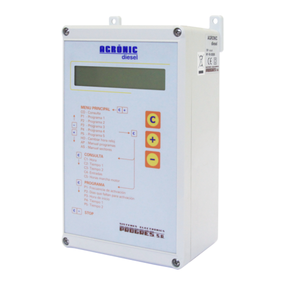
- Page 2 • Figure 1. Keyboard delays workings breakdown detection and external start/stop orders. • Input no.1 used as Start or as Start/Stop. • The fact of relating a time programme with input number 1 (e.g. to start by time and level). 2.
-
Page 3: Technical Caracteristics
3. TECHNICAL CARACTERISTICS Feeding Power source 12Vdc +10% -5% Energy consumption Consumption at stop: 48 mW Maximum consumption: 1,2 W Outlet fuse 4 A, F type, 250V (fast) Outlets Inputs Number Number Type By relay contact, with 12 Type connected VDC power contacts free of power Environment... -
Page 4: Input Connection
until the “C” key is pressed. 5. CONNECTIONS If on giving the order of starting to the engine, it detects that there is oil pressure (that is 5.1. FEEDING CONNECTION to say, it does not receive a signal from the oil pressure gauge through input 3), the programmer Feed the unit at 12Vdc according to figure understands that the motor is already working,... - Page 5 • is normally closed, it will be connected to outlet 3. Outlet 1: Engine start. A supplementary relay, with With the electrovalve normally open, this one is a capacity between 20 and 30 Amps, must be closed during the final time of the working. If the inserted, connecting its outlet to the terminal cable electrovalve is normally closed, this one is opened “50”...
- Page 6 6. CONFIGURATION Figure 7. Configuration diagrams The following graphics show the working of the The installer when starting the system does the outlets according to the chosen option. configuration. Press the “+” and “-” keys at the same time to access it.
- Page 7 CONFIGURATION 5 CONFIGURATION 6 CONFIGURATION 7...
- Page 8 Codes number 12, 13, 14 and 15 are the next codes to be configured. These codes will be completed according to the conditions that have to be fulfilled to start and stop the unit workings. In order to use this table correctly; first read the options until you find the one you are interested in. Then, complete the codes 12, 13, 14 and 15, following the instructions for the chosen option.
- Page 9 stopped manually). element to input 1. by before a change is taken into account at input 1. Connect Enter number The engine The engine The engine starts by external start seconds that have to go starts stops external signal and stops element to input 1.
- Page 10 NOTES: The remaining codes are to be configured next. Table 3 Configuration sections At code 15, if the programme arrives before the input, this one is activated and it proceeds as if the engine was working CODE FUNCTION (programme time goes on). In this way, if input number 1 is Post-irrigation time: is the time in advance activated after the programme has been activated, the remaining the fertilisation must stop before the...
- Page 11 7.2. CONSULTATION (Cx) 7. USE At Consultation we can see the general state of the programmer (breakdowns, conditional stop, time) This chapter is normally used by the user to and, specially, all the information about the evolution programme his/her Agrónic Diesel, once of the programme which is activated.
- Page 12 programmer has started the engine. This spot does has not finished yet or a sector has been activated not appear if the engine has been started without manually. Whatever the problem is, the new using the programmer. programme is the one which is taken into account, This count can start again at 0 using the not paying any attention to the previous one.
- Page 13 7.6. MANUAL SECTORS (AS) 7.9. PROGRAMME PATTERN PROGRAMME 1 This option has just got one section, AS. The screen displays a number which corresponds to the How often it activates sector number which has to be used. Use the “+” and Starting time “-“...
-
Page 14: Function Chart
8. FUNCTION CHART...
Need help?
Do you have a question about the AGRONIC diesel and is the answer not in the manual?
Questions and answers