Table of Contents
Advertisement
Quick Links
Advertisement
Table of Contents

Summary of Contents for icam E Series
- Page 1 E-Series Manual Revision 2.1...
- Page 2 Tel: +44 (0) 1903 892222 Fax: +44 (0) 1903 892277 E-mail: icam@icam.ltd.uk Web: www.firetracer.com COPYRIGHT INFORMATION ICAM Ltd Copyright 2004 This document may not be reproduced, in whole or in Part, by any means without the prior permission of the Coopyright owner.
-
Page 3: Table Of Contents
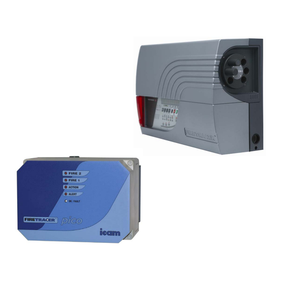
Contents INTRODUCTION Principle of Operation Flow Monitoring Alarms 1 SYSTEM CONTROLS 1.1 The E-Series Display Panel User Functions 2 INSTALLATION 2.1 Mounting Diagrams 2.2 Connection of Cables 2.2.1 FT1, 4, 6, 8, 15 Connections 2.2.2 PICO Connections 2.2.3 Standby Battery (optional) 2.2.4 Operation of the FireTracer e-series from 24 Volts DC only 2.3 Connection of Sampling Tubes 2.4 Power-Up... - Page 4 INTRODUCTION The ICAM e-series is available in several versions, depending on the number of sample tube inlets and build options fitted. All types, except the FT1 and Pico, incorporate a rotary valve enabling individual sample pipes to be selected. Under normal conditions, the FireTracer will monitor all tubes simultaneously.
- Page 5 Alarms The default behaviour of the four Alarm states (ALERT, ACTION, FIRE1 and FIRE2) and TRACE (applicable to FT4 and above) is shown below: IF LATCHED LEVEL DELAY BEACON SOUNDER ON;OFF (sec) TRACE LATCHED 0.03% 3 Seconds Continuous ALERT LATCHED 0.04% 3 Seconds 0.5:2...
- Page 6 1 SYSTEM CONTROLS 1.1 The E-Series Display Panel All of the e-series range, except for the Pico, has a full display panel as seen below. The Pico has no display but instead uses PC based software that emulates the panel and can be used for all monitoring and calibration procedures. This software, detailed in the e-series monitor section (page 37), can be used with all of the e-series and is supplied in all cases.
- Page 7 Individual SAMPLE, ALARM and FAULT indicators for each sector. The ALL Alarm is the TRACE indicator. Function and Fault indicators as follows: POWER Indicates that the power supply is ON GENERAL FAULT The FireTracer has one or more faults, which will also be shown by other specific fault indicators.
-
Page 8: Installation
The cables for the power supply, battery and any I/O modules should be fitted. • The pipe network is fitted to the system. For details on how to design and install a pipe network, see Pipe Installation Manual (ICAM Part No. 09-0003-10) 2.1 Mounting Diagrams Pico Fixings... - Page 9 FT 1/4/6/8/15 Fixings (490.00 (490.00±0.50mm) 0.50mm) 40.00 40.00±0.10mm 0.10mm 320.00 320.00±0.30mm 0.30mm 282.00 282.00±0.25mm 0.25mm Horizontal and vertical configurations FT8/15 FT4/6...
-
Page 10: Connection Of Cables
RS232 connection – Used for conducting Test/Configuration functions and interrogation of the ‘Fault Log Data’ when connected to a Remote User Panel or a PC running ICAM Detmon program The mains power lead should be connected as per the drawing below. - Page 11 Install one on top of the other Connect in series Knock-out cable entry holes M5 Chassis Grounding Stud Battery shelf Ethernet RS232 Fuse 1A ICAM i602 Optional plug-on I/O boards I/O Board Drop-down display panel Programming Beacon Connector Connector Display & valve Connector...
-
Page 12: Pico Connections
TCP/IP stack and can generate html pages for viewing on any Web browser. • RS232 connection – Used for conducting Test/Configuration functions and interrogation of the ‘Fault Log Data’ when connected to a Remote User Panel or a PC running ICAM Detmon program Ethernet RS232... - Page 13 EXTERNAL CONNECTION WIRING TABLE Connections To / From (i602) I/O Board RS232 Communications Receive Data Suitable twisted screened cable up to a maximum distance of 15 Meters Transmit Data 0v Ref See Section 6.0 for further details 1,4,6,7,8,9 No Connection Shell Earth –...
- Page 14 Alert - RL 4 Common Alert - RL 4 Normally Closed Alert - RL 4 Normally Open Fault - RL 5 Common Fault - RL 5 Normally Closed Fault - RL 5 Normally Open Connections To ‘RABBIT’ Processor Board Standard Ethernet cable 8 Pin RJ45 Standard ‘Ethernet’...
- Page 15 Connections From 4 Channel Relay Board (Option Module) Output Relay Connections (i606) RL 1 Common RL 1 Normally Closed RL 1 Normally Open 7x0.2 - 6Amp (24 AWG) Cable RL 2 Common RL 2 Normally Closed RL 2 Normally Open Note : Maximum relay contact rating =2 Amp @ 30v DC RL 3 Common RL 3 Normally Closed...
- Page 16 Connections To Analogue Input Board (Option Module) Input Connections (i625) Input 1 +ve Input 2 +ve Input 3 +ve Inputs 1- 8 = Low Level Inputs Input 4 +ve (As the gain of these Low Level Inputs is build selectable, Input 5 +ve they can on mass be configured as either High Voltage Input 6 +ve...
-
Page 17: Standby Battery (Optional)
(supplied) must be connected and taped to one of the batteries. If batteries are fitted, the internal charger must be enabled. (See the CONFIGURE section; set STANDBY = 1) ICAM recommend the User/Installer fits either:- YUASA – Maintenance Free, Re-Chargeable Lead Acid Battery TYPE: NP 18.0-12 or Equivalent, or YUASA –... -
Page 18: Power-Up
2.4 Power-Up At power-up, the display will first show a rolling text message giving information as to: FireTracer type: FIRETRACER FT [1, 4, 6, 8, 15] Software version: VERSION *.** Optional text 1 Optional text 2 Optional text 3 Optional text information: these are user settable options differing from the factory default settings (1 & 2) or a factory build option (3) REM PANEL The unit may be configured to operate the display panel remotely using the RS485 communications. -
Page 19: Connecting The E-Series Display Panel Remotely
2.6 Connecting the e-series Display Panel remotely An Icam kit is available for mounting the display panel up to 1km away from the FireTracer. It contains: 1 Blanking plate 1 Mounting Box 1 Fixing kit 4 way connector for remote operation... -
Page 20: Setup And Button Functionality
All of the following settings can be entered using the e-series monitor software and a PC. This can cut down the time taken to enter certain values and parameters. To obtain this software contact ICAM or visit the website: www.firetracer.com... -
Page 21: Operator Functions (Operator Code Or Above Required)
3.3 Operator Functions (Operator Code or above required) Enter Operator Mode from the MAIN MENU (or CODE). When the OPERATOR CODE is entered (default = 0), this enables the RESET, SOUNDER SILENCE, and ISOLATE buttons. The unit is placed in the UNLOCK state, as shown by the flashing UNLOCK LED. Otherwise the Character Display will be normal. -
Page 23: Main Menu
3.4 Main Menu Engineering (No Code Required) Certain engineering values may be inspected, primarily for diagnostic purposes. To enter Engineering Mode, follow the following procedure. Action Resulting Note Display Press MAIN MENU OPERATOR Use Parameter UP & DOWN buttons to reach ENGINEERING ENGINEERING Press ENTER VERSION *.**... -
Page 24: Configure
3.4.2 Configure The FireTracer uses many set-up parameters, and is shipped with default values. The Configuration Mode allows changes to be made. Below is a list of user-settable parameters, and their Factory Default values. The Parameter UP and Down buttons navigate through the list;... - Page 25 OPCODE This code (or Access Code Level 1 or 2) must be entered to enable ISOLATE, SOUNDER SILENCE and RESET buttons. The default value is 0. It may be changed within the range 0 to 999, but 260 and 693 should be avoided as these are reserved for Level 1 and 2 access codes.
- Page 26 ADDRESS This is the unit’s RS485 address, required when using ICAMnet. The range is 0 to 30; a value of 31 disables RS485 comms. The default setting is 31 (off). Note that if the display panel is used remotely, communication to it is by means of this RS485 comms port, and the ADDRESS setting is not used.
-
Page 27: Set Sector Day/Night Alarms
3.4.3 Set Sector Day/Night Alarms Press MAIN MENU to enter the Main Menu list from Normal display mode Use Parameter UP & DOWN buttons to reach SECTORS ALMS Press ENTER Enter Level 1 code or above The display will now show DAY VALUES, use Parameter UP & DOWN to change to NIGHT VALUES. Press ENTER to access the settings for all the sectors. -
Page 28: Set Time And Date
3.4.4 Set Time and Date date month year hours minutes seconds Press MAIN MENU to enter the Main Menu list from Normal display mode Use Parameter UP & DOWN buttons to reach TIME DATE Press ENTER Enter Level 1 code or above The display will now show the date (day - date - month - year), with the date flashing. -
Page 29: Set-Up Menu
3.4.6 Set-up Menu To enter SETUP Mode follow the following procedure (also refer to the chart on page 20) Press MAIN MENU to enter the Main Menu list from Normal display mode Use Parameter UP & DOWN buttons to reach SETUP Press ENTER Enter Level 2 code Use Parameter UP &... -
Page 30: I/O Modules
3.5 I/O Modules The e-series has 5 relays fitted as standard. The I/O functionality may be extended by adding I/O modules. These plug onto the standard I/O module in a stackable chain up to 5. They are recognised by the processor as Modules 1 to 5 going from left to right. When installing new modules, the type must be entered in the SETUP menu in order to be correctly recognised. -
Page 31: Channel 4-20Ma Output Module
3.5.2 8 Channel 4-20mA Output Module May be used for retransmission of Flow, Smoke or Gas levels Number of analogue current outputs Maximum output voltage 20 volts Output 1 Output current 4 - 20mA (optionally 0 - 20mA) Output 2 Resolution 16 bits Maximum Integral Nonlinearity... -
Page 32: Channel Analogue Input Module
12 Channel Analogue Input Module SETUP Set to ANIN 12 Input 1+ Input 2+ May be used with various sensors: e.g. gas, humidity, temperature. Input 3+ Input 4+ mV Number of analogue inputs 12 4 - 20mA (input impedance 100 Input 5+ ohms) Input 6+... - Page 33 Ways of setting the Alarm and Pre-alarm thresholds of each analogue input: Case A: High Level Alarm (Condition – Alarm level set above Pre-alarm level) If the input should rise above the Pre-alarm level and remain above this level for more the 10 seconds, then a Pre-alarm condition will be generated by the system.
-
Page 34: Extinguisher Module
3.5.4 2 Extinguisher Module SETUP Set to SUPPR 2 12 Solenoid 1 CONFIGURE Solenoid 2 Designed to release extinguisher gas and operate alarm relays. It also has 2 manual call point inputs, and 2 pressure switch inputs. Relay coil Alarm 1 and contact monitoring is standard. -
Page 35: Installation Guide For Rs 485 Equipment
4 INSTALLATION GUIDE FOR RS 485 EQUIPMENT Communications to RS 485 standard are designed to reject a degree of interference, but care must still be taken when designing and implementing the installation to minimise the level of interference imposed on the equipment. To prevent damage due to tropical storms and other sources of large external currents and voltages, additional surge absorbing components may be required as part of the installation. -
Page 36: Interference Induced On To Cable
4.2.2 Interference Induced on to Cable Twisted pair construction and cable screens do not completely shield the communication link from external electro-magnetic interference. Good practice should be followed when installing communication cables to eliminate problems. RS485 cables should not be installed in the same duct/tray as power cables, or switching cables. When RS485 cables cross power or switching cables, this should be at right angles. -
Page 37: Series Web Server
The figure below shows the main page with the fault and alarm status as well as the smoke detection level. Red values represent a fault. The E-series product, Software Version, date and time are shown at the top of the web page. To send any query to the Icam service support click on the email link. - Page 38 The inputs pages show the status of the fault, fire and gas alarm for each individual sector. To modify a parameter the user must select its list, then pick up the parameter on the next step and finally introduce the new value. The cell must be white to enable the data entry;...
-
Page 39: Series Monitor Software
6 E-SERIES MONITOR SOFTWARE The e-series monitor software provides a method of setting up and calibrating the Pico as well as adding extra functionality to all of the other e-series products. The following procedure is mandatory for setting up the Pico once it has been installed but the software can be used for all of the e-series. -
Page 40: Using The Software
6.4 Using the Software The main program screen is blank except for five buttons in the top left corner as shown below. These access the separate utilities within the program. 6.4.1. E-series display panel emulator This window shows the e-series software emulator. This exactly mimics an e-series display panel and to set-up the Pico, or any of the other e-series range, the buttons on the panel can be clicked on to enter the information in the same way it would be entered if it were a panel on an actual device. -
Page 41: E-Series Configuration Utility
6.4.2. E-series Configuration Utility The window for this utility is shown below: NOTE: All values must be entered with a decimal point (.) even if they are displayed with a comma (,). 1. Main List This list is reproduced on pages 22-24 of this manual with the full titles, range and factory defaults. Some codes are required to change parts of the list and these are supplied in the same section of the manual. -
Page 42: Engineering And Maintenance
4. Environment List If you are using an EnviroTracer to monitor ambient temperature, humidity and/or heat then this table is where the thresholds are entered. The pre-alarm and main alarm can be set to sound at chosen variations from the calibrated value. 5. -
Page 43: Data Logger
6.4.4. Data Logger The window for this utility is shown below: The data logger records every event that occurs with or to the system. The log is constantly added to, with an update rate selected by using the drop-down menu. Other drop-down menus filter the log so specific times and events can be viewed. The event menus are as follows: Update Rate: 5 seconds... -
Page 44: Logging Extraction Application
6.4.5 Logging Extraction Application All log entries stored in the E-Series system can be extracted into an Access database file, by default the EseriesLog.mdb. The EseriesLog.mdb has three tables: EventEnum, EventCategoryEnum and Eventslog. EventEnum stores the event as in the table on the previous page. -
Page 45: Maintenance
7 MAINTENANCE ROUTINE TESTS (Only to be carried out by a trained ‘responsible’ person) The following steps should be carried out DAILY in the case of a free standing system (i.e. where its status is NOT monitored by a main panel or monitoring station), or WEEKLY when the system is monitored. - Page 47 SERVICING (Only to be carried out by Icam trained service engineers) Ensure that all relevant site personnel & supervising authorities have been informed and, where necessary, the system has been isolated from the main building alarm system before undertaking any actions which may result in Alarm and/or Trouble/Fault conditions.
Need help?
Do you have a question about the E Series and is the answer not in the manual?
Questions and answers