Table of Contents
Advertisement
Quick Links
MODEL RT-50A RAIN SENSING WINDSHIELD WIPER CONTROL
1. GET A WIRING DIAGRAM FOR YOUR VEHICLE
Go to www.raintracker.com and click on "Compatibility." Print out any
special installations wiring diagrams that pertain to your car or truck.
If the instructions refer to either the HSS or GSS diagrams included
with this manual, write your specific vehicle
wire colors on the diagram. If the
instructions call for external components,
they are usually included in the
accessory kit.
3. LOCATE THE
WIPER SYSTEM
PARTS
You will likely need to
remove access panels.
You can often trace wires
from the switch or motor,
or listen for clicking relays
when the wiper system is
in intermittent mode.
4. MOUNT THE RAIN TRACKER ACTIVATION SWITCH
The supplied round activation switch turns the Rain
Tracker on to default sensitivity. Mount the switch
before you connect the switch wires to the Rain
Tracker. Select a mounting location in a dash
knock-out panel, or in an under-dash panel
(available at auto parts store.) To mount the round
5. INSTALL THE RAIN TRACKER
INTERFACE MODULE
Make sure the location you select for the
module will not conflict with the
operation of any equipment, such as
accelerator or brake cables. Use the
wiring diagram as a guide in connecting
the Rain Tracker interface module into
the existing wiper system. See last
pages for tips on making connections.
6. INSTALL THE SENSOR
Select a coupler mounting location within the area swept by
the wipers, and out of the shadeband. Just below the mirror
mount is usually a good location. Tip: mark the location with a
piece of masking tape on the outside of the windshield, and
stand back from the vehicle to make sure the mark is level.
Prime the sensor mounting location with isopropyl alcohol.
Do not skip this step! Un-snap the coupler from the sensor.
7. INSTALL THE SENSOR
CABLE
Connect one end of the sensor
cable to the sensor, and route
the cable under the head liner
and down the vehicle's trim to
connect it to the interface
module.
SENSOR
TYPICAL RAIN TRACKER
INSTALLATION
WIPER MOTOR
ASSEMBLY
5A. MAKE THE INTERFACE CONNECTIONS
Connect the wires as shown in the
diagram. If the diagram requires that you
make a chassis ground connection, find a
suitable metal frame member and screw,
and make sure that it is free of paint. Bad
grounds are the most common problems
we encounter when troubleshooting Rain
Tracker installations.
8. SECURE THE
INTERFACE MODULE
Use cable ties to secure the
interface module to a bracket or
convenient location. Reinstall
access panels as needed.
Rain Tracker Model RT-50A Installation Manual - Page 1 of 4
DOCUMENT NUMBER 001-1125-001 A
MODEL RT-50A
INSTALLATION INSTRUCTIONS
2. TEST THE EXISTING WIPER SYSTEM
Make sure that the existing wiper system works in off,
intermittent (if so equipped), slow, and fast modes of
operation, and that the wash motor works.
REARVIEW
MIRROR
AREA SWEPT
BY WIPERS
RAIN TRACKER
EXISTING
ACTIVATION SWITCH
WIPER
SWITCH
WIRING
HARNESS
RAIN TRACKER
INTERFACE MODULE
activation switch, drill a hole (5/8 inch or ¾ inch
depending on switch model supplied) and file the
hole slightly larger until the switch can press in
appropriately. File a locating notch as needed.
Other styles of (SINGLE POLE) switches are
available from Radio Shack and other suppliers.
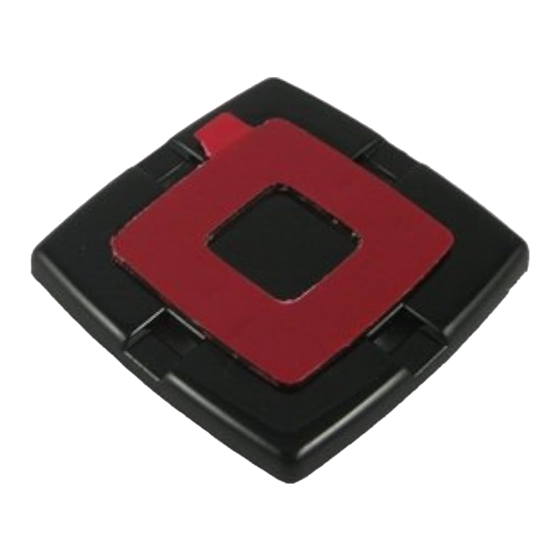
Remove the red protective film
from the coupler, and rock the
coupler onto the windshield.
9. TEST THE RAIN TRACKER SYSTEM WITH A SPRAY
BOTTLE OR GARDEN HOSE
Turn the ignition to accessory mode. Use the wiper control switch
to verify that all manual modes (off, slow, fast, and wash) work.
Put the system in Rain Tracker mode by turning on the activation
switch. Spray a light mist at the sensor and verify that the Rain
Tracker runs the wipers in intermittent mode. Spray more water
and confirm operation in steady slow and fast speeds.
SENSOR CABLE ROUTED
UNDER HEADLINER
SHADE-BAND
SENSOR CABLE
BEHIND PLASTIC TRIM
EXISTING CONTROL MODULE,
BODY-COMPUTER, OR RELAY.
BUILT INTO SWITCH IN SOME CASES
5B. PLUG IN THE INTERFACE MODULE
Plug in the interface connector so that its
locking ramp engages the locking ramp on
the interface module. The BLK ground wire
should be closest to the sensor Jack, J1.
DO NOT PLUG THE INTERFACE MODULE
CONNECTOR IN UPSIDE-DOWN.
Snap the sensor into the
coupler.
Advertisement
Table of Contents

Summary of Contents for RainTracker RT-50A
- Page 1 Tracker runs the wipers in intermittent mode. Spray more water connect it to the interface and confirm operation in steady slow and fast speeds. module. Rain Tracker Model RT-50A Installation Manual - Page 1 of 4 DOCUMENT NUMBER 001-1125-001 A...
- Page 2 SENSOR terminal connects to +12V, with (+12V) motor windings switched to ground. SLOW RELAY DRAWING: FAST RT-50A - GSS RELAY MODEL RT-50A RAIN TRACKER RT-50A IN GROUND-SIDE SWITCHING APPLICATIONS Rain Tracker Model RT-50A Installation Manual - Page 2 of 4...
- Page 3 OPTIONAL LIGHT SENSING / CAM FEEDBACK KIT The Rain Tracker model RT-50A will automatically turn on headlamps at dusk and when it is raining with the addition of LSK-1. This kit is also needed for some CAN bus wiper systems. This kit plugs into the larger three pin connector on the Rain Tracker interface.
- Page 4 HOW THE RAIN TRACKER RT-50A INTERFACE WORKS ACTIVATION - The RT-50A is turned ON by connecting the mode reader AUTOMATIC STEADY FAST - The RT-50A turns on both the slow and the (J2 Pin 3, GRY) is to +12V fast relays.

Need help?
Do you have a question about the RT-50A and is the answer not in the manual?
Questions and answers