Table of Contents
Advertisement
Quick Links
Advertisement
Table of Contents

Summary of Contents for Electronics Technology ES2010E
- Page 1 - 0 -...
-
Page 2: Table Of Contents
CONTENT I.Safety Precautions and Procedures ………………………………………2 II.Introduction …………………………………………………………………3 III.Basic Function Introduction ……………………………………………4 IV.Electrical Symbols …………………………………………………………4 V.Technical Specifications……………………………………………………4 1.Basic Working Condition……………………………………………………4 2.Range and Accuracy Error……………………………………………………5 3.General Specification………………………………………………………5 VI.Structure………………………………………………………………………7 VII.Operation………………………………………………………………………7 1.Switch on/off …………………………………………………………………7 2.Data Hold/Delection…………………………………………………………7 3.Backlight Control ……………………………………………………………8 4.Phase Measurement………………………………………………………………8 5.AC Current、Leakage Current Measurement…………………………………9 6.AC Voltage Measurement………………………………………………………10 7.Perceptual and Capacitive Circuit Discrimination……………………10 8.Frequency Measurement………………………………………………………10... -
Page 3: I.safety Precautions And Procedures
I.Safety Precautions And Procedures Thank you for purchasing our digital double clamp phase voltammeter. Before you use the instrument for the first time, in order to avoid possible electric shock or personal injury, please be sure to: read and strictly observe the safety rules and precautions listed in this manual. -
Page 4: Introduction
u Pay attention to the measuring range and use environment specified by this instrument. u It is forbidden to use, disassemble, calibrate and repair this instrument without permission. It must be operated by authorized personnel. u The " " in the manual is a safety warning sign, and the user must operate safely in accordance with the contents of this manual. -
Page 5: Iii.basic Function Introduction
III. Basic Function Introduction 1. Large screen high backlight display, clear display of the instrument's working status and test parameters, the operation is very convenient. 2. Measure two wire’s voltage, current, phase, and measure grid frequency. 3. Low-current 5mA measurement phase is very suitable for new users to check the connection status after no-load operation, the instrument has high measurement accuracy and wide measurement range. -
Page 6: 2.Range And Accuracy Error
Instrument working 9V±0.1V 9V±1V voltage Voltage amplitude when measuring 220V±20V 30V~500V phase Current amplitude when measuring 2A±0.2A 10mA~20.00A phase External electric field, magnetic Should avoid field Wire position to be The wire under test is in the approximate geometric center of measured the jaw 2.Range and Accuracy Error... - Page 7 Phase range 0.0°~360.0° Frequency 45.00Hz~65.00Hz range Voltage:AC 0.01V Current:AC 0.1mA Resolution Phase:0.1° Frequency:0.01Hz Detection rate About 2 seconds/time Data hold Press HOLD key to hold data during test, "H" symbol display Automatic About 15 minutes after power on, the meter will automatically shut-down shut down to reduce battery consumption Backlight...
-
Page 8: Structure
VI.Structure 1.Insulation anti-vibration sheath 2.LCD display 3.Clamp jaw 4.Current clamp 5.Boot-strap POWRR key 6.Hz key 7.Data hold HOLD key/backlight 8. Functional rotary switch 9. Current clamp input hole ( 2 wires) 10.Voltage input hole (2 wires) 11.Current clamp lead 12. Test wire(Red and black each 2) VII.Operation Before use, carefully check all parts of the instrument for damage, and use them without any damage. -
Page 9: 3.Backlight Control
3.Backlight Control After power on, long press the HOLD button to control the backlight, suitable for dim places. Danger: Electricity! Must operated by the qualified personnel that trained and authorized . The operator must strictly abide by the safety rules, otherwise there is a danger of electric shock, resulting in personal injury or equipment damage. -
Page 10: 5.Ac Current、Leakage Current Measurement
two circuit input circuits are completely isolated and insulated to avoid short circuit and burnout of the instrument. (2). Phase testing of I1I2 Rotate the rotary switch to the I1I2 position. Connect the two current clamps to the I1 and I2 current input jacks on the front of the instrument. Then clamp the current clamp to the I1 and I2 lines. -
Page 11: 6.Ac Voltage Measurement
the rotary switch to the appropriate limit of I2 and use I2 to test the current or leakage current. Note that the positions of the I1 and I2 of the rotary switch must correspond to the input jacks of the current clamps I1 and I2. 6.AC Voltage Measurement Rotate the rotary switch to U1's 600V range. -
Page 12: Various Test Wiring Reference
VIII.Various Test Wiring Reference: - 11 -... -
Page 13: Battery Replacement
IX.Battery Replacement Please pay attention to the polarity of the battery, it must be installed with the correct polarity, otherwise the instrument will be damaged. It is forbidden to replace the battery in hazardous locations Must use a qualified 9V alkaline dry battery 1.When the instrument power supply voltage is lower than 7V, the symbol “... -
Page 14: Other Explanations And Considerations
X.Other Explanations and Considerations 1.Current clamp specificity The two current clamps of the meter are dedicated to this meter and cannot be used for another meter. Current clamp to prevent the impact, the jaw plane must be kept clean, completely closed test is reliable. 2. -
Page 15: Accessories
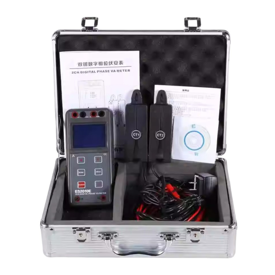
XI.Accessories Host Instrument box Current clamp 2PCS Test line 4 (2 each for red and black) Battery 9VAlkaline battery 1PC Manual, certificate 1SET - 14 -... - Page 16 The company reserves the right to modify the contents of the user manual. If there is any change, it will not be notified. GuangZhou ZhengNeng Electronics Technology Co. Address: 2F, No.15 Baoshu Road, Taihe, Baiyun District, Guangzhou, Guangdong, China Toll-free call:4000-1515-38 Tel:86-20-36544172...
Need help?
Do you have a question about the ES2010E and is the answer not in the manual?
Questions and answers