Table of Contents
Advertisement
HIPAK 2675 BOXMAKER
OPERATOR INSTRUCTION MANUAL
(2008 version with Rubber Roller and Servo Blade Drive)
Updated: December 2007 - KJP
Autobox Ltd, Unit S1 Cherrycourt Way, Leighton Buzzard, Beds. LU7 4UH U.K.
Tel: +44(0)1525-379 359 Fax: +44(0)1525-382 353
e-mail: info@autobox.co.uk. website:
www.autobox.co.uk
Advertisement
Table of Contents

Summary of Contents for Autobox HIPAK 2675
- Page 1 HIPAK 2675 BOXMAKER OPERATOR INSTRUCTION MANUAL (2008 version with Rubber Roller and Servo Blade Drive) Updated: December 2007 - KJP Autobox Ltd, Unit S1 Cherrycourt Way, Leighton Buzzard, Beds. LU7 4UH U.K. Tel: +44(0)1525-379 359 Fax: +44(0)1525-382 353 e-mail: info@autobox.co.uk. website: www.autobox.co.uk...
-
Page 2: Table Of Contents
CONTENTS Introduction Installation Safety . Box Styles Operator Controls Main Menu Make a New Box Screens 10-11 Feeding Blanks Making Base/Lid Boxes Making 0933 Divisions Making Flip-Top Boxes The Self-Design (12-Slot) Program . Using the Auto-Feeder Calibration 15-17 Error Messages Trouble Shooting Maintenance . -
Page 3: Introduction
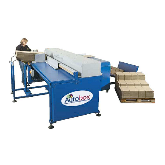
INTRODUCTION The Autobox HIPAK 2675 Boxmaker is a sophisticated machine for conversion of various corrugated board grades into cartons. It is designed for conversion of all grades of single-wall corrugated and up to 300K/300T AA double-wall. The Boxmaker utilises a powerful PC with colour touch-screen to reduce the effort of calculation and set-up time to a minimum. -
Page 4: Installation
DISMANTLING If for any reason, the machine has to be dismantled or removed, full details of the correct procedure may be obtained by contacting The Technical Department at Autobox Limited. Under no circumstances must a person dismantle the machine without instructions being... -
Page 5: Safety
Autobox engineer. Please ensure that the electrical supply is disconnected before removing guarding for any reason. If there is... -
Page 6: Box Styles
Box Styles Programmed into the HIPAK 2675 Boxmaker ½SC... -
Page 7: Operator Controls
OPERATOR CONTROLS EMERGENCY STOP Switch to adjust ‘Setting 2’ Feeder Gate Large Counter Crease Lever Left-Hand Guide Touch Screen Small Counter Conveyor On/Off Crank Handle to and speed adjust adjust ‘Setting 1’ Primary 3-Phase Isolator and Start/Stop CONTROL FUNCTIONS. TOUCH SCREEN The touch screen is the Human-Machine Interface used to select box style, input dimensions, monitor progress, store and read back boxes, etc. - Page 8 RATING PLATE The rating plate, fitted to the end panel, displays Model number, Serial number, manufacturer contact details, power requirements, etc. This information will be required by Autobox in the event of any enquiry concerning service or spare parts.
-
Page 9: Main Menu
MAIN MENU This will appear when the machine is first started. Return to Main Menu at any time by touching the ‘Menu’ button or the ‘Back’ button TO MAKE A NEW BOX Touch ‘Make New Box’ in menu. Touch required box style or ‘menu’ to go back Select variant where available Touch ***** to enter dimensions and numeric keypad will appear on screen... -
Page 10: Screens
SCREENS The ‘Run’ screen is displayed while making boxes. It displays the time and date, the box style being made and the number made. It also allows the operator to select several options including; save the current box to memory, check the dimensions entered, adjust the throughput speed or return to the ‘Main Menu’. - Page 11 SAVING BOXES INTO MEMORY Touching ‘Save’ will allow the current box to be entered into the memory for future use. The virtual alpha-numeric keyboard can be used to give each box a code, or name, for identification. MEMORY The memory can be accessed via the main menu or from other screens by touching the button.
-
Page 12: Feeding Blanks
FEEDING IN THE BLANKS. The blanks (already cut to the correct size) must be fed into the machine held gently against the left-hand guide to keep them square and must have the inside of the box (the test or liner) facing up. The right-hand guide is provided to help keep the blanks square. This should be locked in place leaving 1 or 2mm clear to allow the blanks to slide freely into the machine. -
Page 13: Making Flip-Top Boxes
TO MAKE FLIP TOP BOXES. Enter dimensions as for other box styles but note the following: The flip top flap is 75mm when the height is 60mm or less. When the height is over 60mm, the flap will be 125% of the height. Minimum length is 155mm. The flip-top box is measured as shown. -
Page 14: Using The Auto-Feeder
USING THE AUTO FEEDER (IF FITTED) The automated sheet feeder fitted to your HIPAK consists of a free-standing board support, as well as the gates, guides and roller assembly on the front table-top. To operate the feeder, first cut the blanks to size and set up the machine guide and moving blade as described in the previous pages. -
Page 15: Calibration
Hipak 2675/2670 Calibration procedure As with any electro-mechanical machine, the electronics and mechanics have to be synchronised to gain maximum performance and accuracy. The following are instructions for calibrating a Hipak machine with ‘Generation 7’ touch screen control system. This should normally only be carried out when the machine is first built but, following servicing, repairs or software upgrades, some further calibration may become necessary. - Page 16 ‘Move Test’ This is normally only used by Autobox engineers to check encoder calibration. Touch ‘Switch Controller Off’ and push a suitable length of board into the machine. Select ‘Board Encoder’ or ‘Motor Encoder’. Select suitable Move Distance, Accel/Decel rate and Board Speed (Nominal 50%).
-
Page 17: Error Messages
‘Change Password’ This enables the owner to enter a password of personal choice. Any personal password must be made available to Autobox engineers when needed. ‘Select Motor’ This enables the drive system to be configured to operate with an alternate motor. -
Page 18: Troubleshooting
TROUBLESHOOTING In the unlikely event that your boxmaker does not operate as expected please check the following: BOARD NOT ACCEPTED BY MACHINE. Check that you have fully programmed machine and it is showing a ‘READY’ prompt. Check that dust or particles of board are not obstructing the light sensors. If this is suspected then, from ‘Main Menu’... -
Page 19: Maintenance
MAINTENANCE Normal housekeeping procedures should be employed to keep the machine clean and dry. Some basic adjustments and maintenance procedures are detailed in the following pages. DAILY: Purge the machine of dust using a suitable vacuum cleaner around the blade and sensor area or blow out with an airline if safe to do so. -
Page 20: Sensors
SENSORS Two optical sensors are fitted to the machine to detect the corrugated board entering and leaving the machine. The sensor consists of a 24Vdc amplifier unit with digital display, mounted at the top left corner of the machine, and a fibre-optic cable that is mounted such that the end of the cable ‘sees’... -
Page 21: Wiring Schematic
240Vac Single Brown Phase Supply Blue From Isolator 13A Fused Terminal Printer Supply Sockets 5A Fused 37E Speed Control Board (Connections viewed from rear) Terminal Blue Printer Supply 1 2 3 4 5 A- A+ F- F+ N L Neon Rocker Switch Switch Auto Feeder Motor... - Page 22 415Vac 3-phase supply from Primary Isolator From PSU V1016 Roller Drive Unit E L3 L2 L1 (ACOPOS) PP220 Touch Screen Blue EX270 – I/O Unit (Detail) Plug 7AC911.9 To Servo Drive AC110 card Trigger from Link Blue I/O Unit; 3 - High - Red Terminal X1 : 4 4 - Ground - Green Green...
- Page 23 24V toggle Top Beam Relay 1 switch for Black Terminal Rear limit switch blade Block Capacitor adjust Black Brown Yellow Brown Blade Yellow Brown Brown Adjust Brown Black Motor Brown Grey Front limit switch Blue Blue Blue White Relay 2 Blue Transformer 24Vac...
- Page 24 Emergency Stop Switch Black 415V 3-Phase Supply to 415V 3-Phase Supply ACOPOS Roller Drive to Lexium Blade Drive 3 Phase Input / Isolator Unit Servo Servo Primary Black Incoming Supply: 415 Volts 20 Amps 3 Phase A1 1 3 5 13 A2 + Neutral L1 L2 L3 N + Earth...
- Page 25 Servo Blade Drive 415Vac 3-phase Supply from Fuse Bank 1 2 3 4 Brown Blade Proximity Black Sensor Blue Lexium 15LP Trigger from I/O unit Terminal X2 : 3 Blade Drive Unit Engineer Connection Point on frame (For inching) Primary Earth - 0Vdc From PSU...
-
Page 26: Service Spares
PARTS IDENTIFICATION Blades and Sensors (Front Top Cover Removed) Blade Edge Rear Sensor (2600/045C) Fibre Optic Unit Blade Tail (2600/045B) Crease Wheel Encoder Rubber Roller Front Sensor Fibre Optic Unit Blade Drive (Rear Lower Covers Removed) Servo Unit Ballast Resistor Blade Drive Motor Belt and... - Page 27 Electrical Cabinet 37E Speed Control Fused Card for Conveyor Terminal Connectors Earth Terminal Input/Output Unit (I/O) Relays Power Supply Unit (PSU) 24V Transformer Transport Motor (Rear Lower Cover Removed) Belt Servo Motor Gearbox Servo Drive (R/H End Cover Removed) Linear Shaft ACOPOS Servo Drive Linear Bearing...
-
Page 28: Replace Compact Flashcard
TO REPLACE THE FLASHCARD IN A HIPAK (Software upgrade) The Compact Flashcard containing the software is fitted into a communications slot in the side of the Power Panel (screen). To access this, first disconnect the power supply and remove the four screws in the front of the metal enclosure taking great care not to allow the enclosure to fall. -
Page 29: Warranty
WARRANTY Products manufactured by Autobox Limited are covered by warranty against faulty workmanship and materials for a period as defined at the time of purchase providing that: a. The equipment has not been subjected to any form of abuse, misuse or damage howsoever caused. -
Page 30: Ce Conformity Certificate
93/68/EEC and the requirements of the Electromagnetic Compatibility Directive 89/336/EEC, 91/263/EEC and 92/31/EEC. Machine Model ………HIPAK 2675AF………………… Machine Serial No…………………………………………. Manufactured By Business name: AUTOBOX LIMITED Address: UNIT S1, CHERRYCOURT WAY, LEIGHTON BUZZARD, BEDS. LU7 4UH U.K. The following transposed harmonised European Standards have been used: EN292 parts 1 and 2: 1991 Safety of Machinery - Basic concepts, general principles for design. -
Page 31: 3-Phase Wiring
WIRING INSTRUCTIONS – HIPAK 2675 ALL ELECTRIC 3 PHASE ISOLATOR/STARTER 1. LIFT CLIPS TO REMOVE FRONT COVER. 2. FEED 3 PHASE CABLE THROUGH GLAND. 3. CONNECT EARTH L1 L2 L3 N WIRE TO BLOCK ON EARTH SIDE. 4. CONNECT 3 LIVES AND NEUTRAL AS SHOWN.
Need help?
Do you have a question about the HIPAK 2675 and is the answer not in the manual?
Questions and answers