Table of Contents
Advertisement
Quick Links
Advertisement
Table of Contents

Summary of Contents for McAnax MIG-160E
- Page 1 Operator’s Manual Inverter DC MIG Welder (MIG-200) With LED Display Warning! This machine should be operated and maintained by competent or professionals. Repairs should only be carried out after reading the manual Inverter DC MIG Welder Manual www.genfitt.ie...
-
Page 2: Table Of Contents
CONTENTS Safety……………………..………………..……………………....... General Description………..………………..……………………......Main Parameter………..………………..………………..……....... Structure of Welder……..………………..….…………………......Installation…………..…...……………..……………………........Welder Settings Quick Reference Chart..………………..………………... Range of Welding Current and Voltage in CO2 Welding………..………... Welding parameters table………......……..………….……... Caution…………..…...……………..……………………........Maintenance………..…...……………..………………........Daily Checks………..…...……………………………..........Connection Diagram of the Machine…………..………........Exploded Diagram..…..………………..….…………………......Plug Installation..…..………………..….…………………......Inverter DC MIG Welder Manual www.genfitt.ie... -
Page 3: Safety
SAFETY Welding and cutting is dangerous to the operator, people in or near the working area and the surrounding area, if the machine is not correctly operated. Therefore, the performance of welding/cutting must only be under the strict and comprehensive observance of all relevant safety regulations. -
Page 4: General Description
GENERAL DESCRIPTION This welding machine is composed of the inverter MIG welder power supply with invariable voltage output external characteristics manufactured with advanced IGBT inverter technology designed by THE company. With high-power component IGBT, the inverter convert the DC voltage, which is rectified from input 50Hz/60Hz AC voltage, to high-frequency 20-50KHz AC voltage;... - Page 5 GENERAL DESCRIPTION Operating environment Adequate ventilation is required to provide proper cooling for the MIG machine. Ensure that the machine is placed on a stable level surface where clean cool air can easily flow through the unit. The MIG machine has electrical components and control circuit .boards which will be damaged by excessive dust and dirt, so a clean operating environment is essential.
-
Page 6: Main Parameter
MAIN PARAMETER 5KG Wire Spool Models MODEL MIG-160E MIG-200E Power Supply 220±10% 220±10% Voltage Rated Input Capacity Rated Input Current Output Current 50-160 10-160 10-150 50-200 10-200 10-160 Range Function 30% 160A 30% 160A 30% 150A 20% 200A 20% 200A 20% 160A Duty Cycle(40℃... -
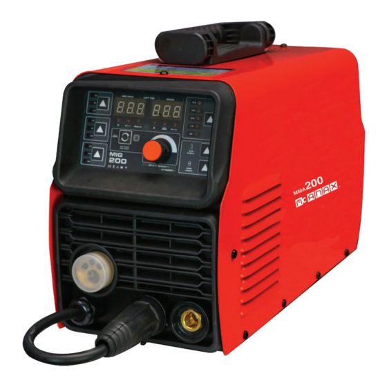
Page 7: Structure Of Welder
STRUCTURE OF WELDER Voltage Meter\Voltage refine Meter Gas selection button VRD/2T/4T selection button Welding mode selection button Amperage\Inductance\Wire-feeding Speed Meter Wire diameter selection butoon Gas check button Wire check button Spool gun button Multifunction knob MIG Torch ‘Euro Style’ Connection Socket Positive (+) Welding Output Terminal Negative (-) Welding Output Terminal Polar conversion line... - Page 8 STRUCTURE OF WELDER Torch trigger switch Torch “Euro” connector Work piece earth clamp Earth lead quick connector Conical gas nozzle/shroud Welding tip Shroud spring Tip adapter 4.3 Welding parameters Torch trigger switch Torch “Euro” connector Work piece earth clamp Earth lead quick connector Conical gas nozzle/shroud Welding tip Shroud spring...
-
Page 9: Installation
INSTALLATION 5.1 MIG Welding Set Up & Operation 5.1.1 Fitting the spool 5.1.1.1 Open the cover door for the wire feed compartment. Remove the wire spool retainer (24) by threading off anti clockwise. 5.1.1.2 Fit the 200mm diameter wire spool to the spool holder, ensuring the end of the wires exits towards the wire feeder from the bottom of the spool. - Page 10 INSTALLATION Warning! - Before changing the feed roller or wire spool, ensure that the mains power is switched off Warning! - The use of excessive feed tension will cause rapid and premature wear of the drive roller, the support bearing and the drive motor. 5.1.3 Loading wire feeder 5.1.3.1 Connect the MIG Torch Euro Connector (28) to the torch socket on the front of the welder (11).
- Page 11 INSTALLATION 5.1.5 Setup for MMA/STICK mode operation Note - MMA/Stick Welding requires an MMA lead set. 5.1.5.1 Connect Electrode holder Quick Connector to the positive (+) welding output terminal (12). 5.1.5.2 Connect Earth Lead Quick Connector (30) to the negative (-) output welding terminal (13). See picture below: 5.1.6 Setup for Lift TIG welding operation Note - TIG operation requires an argon gas supply, TIG torch, consumables.
- Page 12 INSTALLATION Connection of Shield Gas Connect the CO2 hose, which come from the wire feeder to the copper nozzle of gas bottle. The gas supply system includes the gas bottle, the air regulator and the gas hose, the heater cable should be inserted into the socket of machine’s back, and use the hose clamp to tighten it to prevent leaking or air-in, so that the welding spot is protected.
- Page 13 INSTALLATION 5.1.5 Controls for MIG Welding 5.1.5.1 Voltage meter: in MIG mode it shows setting voltage and welding voltage; in other modes no voltage will be showed. 5.1.5.2 Gas selection: CO2--ordinary CO2 gas; MIX--20% CO2 80% argon; FLUX-- flux cored. 5.1.5.3 Function selection: 2T in MIG mode/4T in MIG mode;...
- Page 14 INSTALLATION 6 Welding settings quick reference chart Inverter DC MIG Welder Manual www.genfitt.ie...
- Page 15 INSTALLATION Basic welding guide MIG (GMAW/FCAW) Basic Welding Technique Two different welding processes are covered in this section (GMAW and FCAW), with the intention providing the very basic concepts in using the MIG mode of welding, where a welding gun is hand held, and the electrode (welding wire) is fed into a weld puddle, and the arc is shielded by an inert welding grade shielding gas or inert welding grade shielding gas mixture.
- Page 16 INSTALLATION Position of MIG Torch The angle of MIG torch to the weld has an effect on the width of the weld. The welding gun should be held at an angle to the weld joint. (See Secondary Adjustment Variables below) Hold the gun so that the welding seam is viewed at all times.
- Page 17 INSTALLATION DISTANCE FROM THE MIG TORCH NOZZLE TO THE WORK PIECE. The electrode wire stick out from the MIG torch nozzle should be between 10mm TO 20.0mm. This discharge may vary depending on the type of joint that is being welded. TRAVEL SPEED The speed at which the molten pool travels influences the width of the weld and penetration of the welding run.
- Page 18 INSTALLATION Establishing the Arc and Making Weld Beads Before attempting to weld on a finished piece of work, it is recommended that practice welds be made on a sample metal of the same material as that of the finished piece The easiest welding procedure for the beginner to experiment with MIG welding is the flat position.
-
Page 19: Range Of Welding Current And Voltage In Co2 Welding
INSTALLATION 7. Range of welding current and voltage in CO2 welding Short circuit transition Granular transition Wire O (mm) Current (A) Voltage (V) Current (A) Voltage (V) 40 ~ 70 17 ~ 19 160 ~ 400 25 ~ 38 60 ~ 100 18 ~ 19 200 ~ 500 26 ~ 40... - Page 20 INSTALLATION Plate Wire Welding Gas volume thickness Welding Welding g (mm) O (mm) speed (L/min) t (mm) current (A) voltage (V) (cm/min) 0.8~0.9 60 ~ 70 16 ~ 16.5 50 ~ 60 0.8 ~ 0.9 75 ~ 85 17 ~ 17.5 50 ~ 60 10 ~ 15 70 ~ 80...
- Page 21 INSTALLATION Plate Corn size Wire Welding Gas volume Welding Welding thickness t (mm) I (mm) O (mm) speed (L/min) current (A) voltage (V) (cm/min) 2.5 ~ 3.0 0.8~0.9 70 ~ 80 17 ~ 18 50 ~ 60 10 ~ 15 2.5 ~ 3.0 70 ~ 100 18 ~ 19...
- Page 22 INSTALLATION Plate Corn size Wire Welding Gas volume Welding Welding thickness t (mm) I (mm) O (mm) speed (L/min) current (A) voltage (V) (cm/min) 2.5 ~ 3.0 70 ~ 100 18 ~ 19 50 ~ 60 10 ~ 15 2.5 ~ 3.0 1.0 ~ 1.2 90 ~ 120 18 ~ 20...
-
Page 23: Caution
CAUTION 1. Working environment 1. Welding should be carried out in a relatively dry environment with its humidity of 90% or less. 2. The temperature of the working environment should be within -10 C to 40 C. 3. Avoid welding in the open air unless sheltered from sunlight and rain, and never let rain or water infiltrate the machine. -
Page 24: Maintenance
MAINTENANCE 1. Disconnect input plug or power before maintenance or repair on machine. 2. Be sure input ground wire is properly connect to a ground terminal. 3. Check whether the inner gas-electricity connection is well (esp. the plugs), and tighten the loose connection; if there is oxidization, remove it with sand paper and then re-connect. -
Page 25: Daily Checks
DAILY CHECKS To make best use of the machine, daily checking is very important. During the daily checking, please check in the order of torch, wire-feeding vehicle, all kinds of PCB, the gas hole, and so on. Remove the dust or replace some parts if necessary. - Page 26 DAILY CHECKS 11.2. Welding torch Part Check Remarks 1. Check if the nozzle is fixed firmly and Possible gas leakage occurs due to distortion of the tip exists. the unfixed nozzle. Nozzle Spatter possibly leads to the damage 2.Check if there is spatter sticking on the of torch.
- Page 27 DAILY CHECKS 11.3. Wire feeder Part Check Remarks 1.Check if the pressure-adjusting han- Pressure adjusting The unfixed pressure-adjusting handle dle is fixed and adjusted to the desired handle leads to the unstable welding output. position. 1. Check if there is dust or spatter inside Remove the dust.
-
Page 28: Connection Diagram Of The Machine
CONNECTION DIAGRAM OF THE MACHINE 12. . CONNECTION DIAGRAM OF THE MACHINE Inverter DC MIG Welder Manual www.genfitt.ie... - Page 29 EXPLOSION DRAWING 13.1 MIG-160E/200E PART NAME CONSUMABLES NO. PART NAME CONSUMABLES power cable front panel wire buckle upper plastic panel solenoid valve knob downward plastic power switch panel upper plastic panel downward plastic panel real panel fan support clapboard machine cover...
-
Page 30: Plug Installation
PLUG INSTALLATION PLUG INDUSTRIAL 16amp BLUE 3 PIN 240V • Always switch off power before changing plugs • Tighten all terminals and connections • If in doubt ask a qualified electrician Wiring instructions: Mains / flexible power cable • BROWN: Connect to terminal marked Live or L •...
Need help?
Do you have a question about the MIG-160E and is the answer not in the manual?
Questions and answers