Table of Contents
Advertisement
Quick Links
G7-3865U Brief Instructions
Notice: For safety reasons, make sure that the computer has been
.A
disconnected from the power supply before opening it.
1. Open the computer
Please remove the four fl『st Screw In the
corners of the base plate (see Image 1)
and lift carefully remove It from the
0
computer.
(
甸
。
—
—
。
,
一
0
到
J
一
「
Image 1
2. Installation of the main memory (RAM)
Align the notch on the memory module with the tab In
the memory socket.
■■■■
carefully push
e memory module In 45-<legree angle
中
lnlo the slot
Now p
ess
e module down
unUI ii
(1).
(2)
小
『
clicks Into place
Foll
this process for each RAM
(3).
叩
module to be Installed.
兰
石��
l
""""'""
"""'"�
Setting up the system - Hardware
3. Installation of mPCle modules
The computer contains one slot for mSATA
module(see M2) and one for another mPCle
module(see MS) .
Align the notch on the respective memory module with the tab In
the corresponding memory
et. Press one for another mPCle
吵
module(see M2). Then carefully Insert the module Into the slot at
a 45-degree angle. Now press the module down and fasten It with
asmall sa
In the cylinder provided for this purpose.
如
4. Installation of a ha『d disk
The computer has a space on its base plate for a
2.5 "SATA hard dlsk(see U3). Here a hard disk
(HOD/ SSD) is fastened from the inside with
four screws(see Image 4) and with the power
and data cable(see M3 and M4).
I - —
0 0
0 0
Image 4
Completion of the hardware assembly
5.
Put the base plate back on the computer. Place
them so that the ha
d drive is on the inside and
『
the four rubber feet are on the outside. Then
tighten the four screws In the corners again.
A
Notice: When starting, please press the "Del" key and load
the BIOS and load the "optimized" settings.
A
Notice: The Driver of this computer is backed up in the
���i:e· : Careless battery
eplacement can damage this
A
『
computer. Replace only with one of the same type. Dispose
of used batteries according to the manufacturer's
instructions.
G7-3865U Brief Instructions
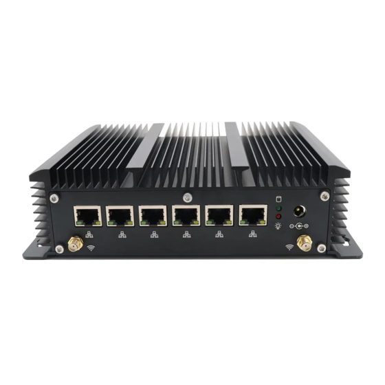
A. Front
B. Rear
C. Underside
一
心
lo
"E
A
Notice: The computer can be
and
vertically.
With
horizontal
computer
run
without the
F1: USB 3.0 ports(4 pieces)
F2: D89 RS232 COM(1 piece)
F3: RJ45 RS232 COM(1 piece)
F4: HDMI display ports(1 piece)
F5: Reset button(1 piece)
F6: Power On/Off Switch
R1: RJ45 Giga LAN(6 pieces)
R2: Power LED(1 piece)
R3: HOD LED(1 piece)
R4: Power supply socket(12V DC IN)
RS: Holes for WLAN antennas
U 1: Screw openings for hard disk(HDD / SSD 2.5 "SAT A)
M1: Socket for RAM modules
M2: Socket for mSATA SSD
M3: Power cable for hard disk(HDD / SSD 2.5 "SATA)
M4: Data cable for hard disk(HDD / SSD 2.5 "SATA)
MS: Socket for mPCle (e.g. WLAN)
M6: SIM Card Slot
M?: CR2032 button battery
MB: Guaranty Segel
D. Mainboard
operated
hori z ontally
us ,
e
NE
VER let
the
rubbe
feet.
『
GREEN
IT
三
©
CE
Advertisement
Table of Contents

Summary of Contents for eglobal G7-3865U
- Page 1 G7-3865U Brief Instructions Setting up the system - Hardware G7-3865U Brief Instructions A. Front F1: USB 3.0 ports(4 pieces) Notice: For safety reasons, make sure that the computer has been GREEN disconnected from the power supply before opening it. 三...
- Page 2 Smart Computers IMPORTANT INFORMATION: 1. Download Center You will find all the important information, tools and drivers for the mini-PCs on our website and in our download center. Link: www.egsmtpc.com Flyer download and access to the Download Center at the bottom left. 2.
Need help?
Do you have a question about the G7-3865U and is the answer not in the manual?
Questions and answers