Table of Contents
Advertisement
Quick Links
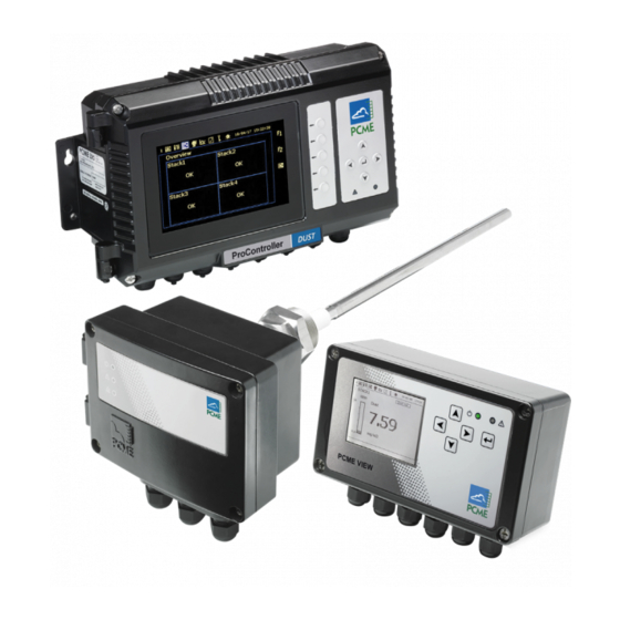
PCME STACK 990
The products described in this manual are subject to continuous development and improvement
and it is, therefore, acknowledged that this manual may contain errors or omissions. PCME
encourage customer feedback and welcome any comments or suggestions relating to the product
or documentation. These should be forwarded to the Technical Department at the address given
below.
This manual is intended as a guide to the use and installation of the product and, therefore,
PCME Ltd. shall not be liable for any loss or damage whatsoever arising from the use of any
information or details therein, or omission or error in, this manual, or any miss-use of the
product.
USER MANUAL
PCME Ltd
Clearview Building
60 Edison Road
St Ives Cambs UK
PE27 3GH
Tel
+44 (0) 1480 468200
Fax
+44 (0) 1480 463400
Email: contact@pcme.co.uk
www.pcme.co.uk
- PCME STACK 990 MANUAL: 1 -
Advertisement
Table of Contents

Related Manuals for PCME STACK 990

Summary of Contents for PCME STACK 990
- Page 1 This manual is intended as a guide to the use and installation of the product and, therefore, PCME Ltd. shall not be liable for any loss or damage whatsoever arising from the use of any information or details therein, or omission or error in, this manual, or any miss-use of the product.
- Page 2 - PCME STACK 990 MANUAL: 2 -...
-
Page 3: Table Of Contents
Bus Termination Switch (SW200) ................25 RS232/RS485 Connections (PL2) ................25 Digital Input Connections (PL3) ................25 4-20mA Output Connections (PL4)................26 Alarm Contact Connections (PL5) ................26 Power Supply Connections (PL6) ................27 - PCME STACK 990 MANUAL: 3 -... - Page 4 QUALITY ASSURANCE AND SELF TESTS ............55 ....................... 55 NTRODUCTION PCME STACK 990 S ................ 56 ENSOR ESTS Zero check and Span Checks.................. 56 Short Circuit Check ....................56 Contamination Ring Check ..................56 - PCME STACK 990 MANUAL: 4 -...
- Page 5 More Sensor Settings .................... 74 Basic System Setup....................75 Other Functions....................76 QA and Calibration....................77 Document Control Information SOP Reference PCME STACK 990 Issue No Issue Date 21/07/09 Software Version 7.00 Filename PCME STACK 990 v3.doc - PCME STACK 990 MANUAL: 5 -...
-
Page 6: Introduction
The procedures given in this manual must only be carried out by suitable trained and qualified personnel. 1.2 Disclaimer PCME Ltd. will not be liable for any injury or damage caused by incorrect installation, set-up, operation or maintenance resulting from a failure to follow the procedures given in this manual. 1.3 Product Safety... -
Page 7: Danger From Process
The following abbreviations are used in this manual: Auxiliary Input Module Analogue Output Module Power Supply Unit Relay Output Module 1.7 Associated Documents Control Unit Reference Manual Installation of Network Devices: Reference Manual PCME Installation Notes - PCME STACK 990 MANUAL: 7 -... -
Page 8: Product Description
Ensure opening/hole in stack wall is at least 45mm diameter Power requirements 24V provided by the control unit RS-485 connection to control unit Local outputs Optional: 4-20mA (250 Ohm, non-isolated) Optional: relay (1A @ 30V) Cable entries 3 x M20 gland/conduit entries - PCME STACK 990 MANUAL: 8 -... -
Page 9: Sensor Options
Cable type 4 core screen (see installation section for details) May be required on some applications (consult PCME). Air Purge requirements Requires optional air purge fitting and an external supply of 5-10 litres/min of dry clean, oil free instrument air... -
Page 10: Sensor Accessories
1 x RS-485 (Modbus RTU) 1 x RS-485 (Modbus RTU) 1 x 4-20mA (500 ohm) 4 x 4-20mA (500 ohm) Outputs 2 x Relay (2A@250V, user 4 x Relay (2A @250V, user selectable) selectable) - PCME STACK 990 MANUAL: 10 -... -
Page 11: System Options
4 x 4-20mA inputs Analogue input module (AIM) 4 x Digital inputs Analogue output module (AOM) 8 x 4-20mA (500 Ohm) Alarm output module (ROM) 8 x Relay (1A @ 250V) Isolating Spur Provides Surge protection - PCME STACK 990 MANUAL: 11 -... -
Page 12: Sensor Installation
Probe damage may result in inaccurate measurements. Supply Voltage The sensor operates at 24V DC supplied from the Control Unit. 3.2 Data Cabling Specification The cabling provided by PCME has the following specification: • 2 pair (4 core), 0.5mm •... -
Page 13: Installation Guidelines
For large systems it is best to place the control unit in the centre of the network to minimise voltage drop along cables. For large systems you may need to boost power using a Power Supply Repeater – contact PCME for details. - Page 14 4-core Power (24V DC)/ Comms (RS485) 115/230V AC Figure 3-1 Standard System 4-core Power (24V DC)/ Comms (RS485) 115/230V AC 4-core Power (24V DC)/ Comms (RS485) Figure 3-2 PLUS System (“Spur Linked”) - PCME STACK 990 MANUAL: 14 -...
-
Page 15: Fitting The Sensor To The Stack
Figure 3-4 PCME STACK 990 Probe Stack wall Contamination ring Stack wall hole for probe (Ø at least 45mm) 1.5” BSP thread Weld all round Floating nut 1.5” BSP socket Lock nut Probe rod Sensor enclosure Insulator - PCME STACK 990 MANUAL: 15 -... -
Page 16: Electrical Connection
BUS OUT terminals. Make the connections to the BUS OUT terminals as follows from left to right: Blue BUS OUT TERMINAL Comms B Orange *Connect the cable screen to the Comms A Green earth stud Brown (Screen) Do not use* - PCME STACK 990 MANUAL: 16 -... - Page 17 Figure 3-5 PCME Stack 990 Sensor Unit BUS OUT(power and comms) Contamination probe Contamination probe enable/disable BUS IN(power and comms) (shown enabled) 4-20mA and relay outputs (option) Bus termination switch (SW200) Set comms switch (SW101) Main probe enable/disable switch (shown enabled)
-
Page 18: Cable Routing
The Bus Termination Switch (SW200) identifies the sensor’s position in the network. Set the switch to “U” for all sensors in the chain except the last sensor, which must be set to T. For spur- systems leave all sensors terminated (switch to “T”). - PCME STACK 990 MANUAL: 18 -... -
Page 19: Set Address Switch (Sw100)
RTU is a faster communications protocol but is not available for all devices; refer to the Control Unit Reference Manual. If RTU mode is required set the DIP switch as follows: Refit the Sensor Cover and secure with the four screws. Do not over tighten the screws. - PCME STACK 990 MANUAL: 19 -... -
Page 20: Multi-Controller Installation (Plus Version)
EARTHING THIS EQUIPMENT MUST BE EARTHED NO User Serviceable parts within. If the equipment is used in a manner not specified by the manufacturer, the protection provided by the equipment may be impaired. - PCME STACK 990 MANUAL: 20 -... -
Page 21: Tools And Materials
Template Height 110 mm ** the mounting holes are elliptical to allow flexibility of position Data Cabling Specification Data cabling for the MultiController provided by PCME meets the following specification: • 2 pair (4 core), 0.5mm • BS5308 part 2, type 1 •... -
Page 22: Location Requirements
1. Cable entry gland (8 off) Power-on indicator alarm indicator 2. Back-lit graphical display (320 x 240 pixels) 5. Cursor keys (up, down, left, right) 3. Front cover securing screw (4 off) 6. Enter key - PCME STACK 990 MANUAL: 22 -... - Page 23 5 Digital inputs terminals (PL3) 11 Fixing hole (4 off) 6 Earth stud - cable screen (3 off) Mains fuse rating: Quick blow, rated 240VAC 1A, with 1500A interrupt capability, HRC ceramic, UL-recognised - PCME STACK 990 MANUAL: 23 -...
-
Page 24: Installation
Route the data cable for one half of the network through the cable gland nearest to the Data Bus PL1 and make the connections to the Data Bus PL1. - PCME STACK 990 MANUAL: 24 -... -
Page 25: Bus Termination Switch (Sw200)
Route a suitable cable through a vacant cable gland and connect to PL3 as shown. The connection should be made between the required input and common ground. - PCME STACK 990 MANUAL: 25 -... -
Page 26: 4-20Ma Output Connections (Pl4)
Relay 4: Self-test alarm Relay contacts are shown in the normal operating positions- power is applied and no alarm exists. Route a suitable cable through a vacant cable gland and connect to PL5 as shown. - PCME STACK 990 MANUAL: 26 -... -
Page 27: Power Supply Connections (Pl6)
Refit the unit cover and secure with the four screws. Do not over tighten the screws. Carry out the initial set-up procedures given in the Initial Setup section. - PCME STACK 990 MANUAL: 27 -... -
Page 28: Interface Module Installation
EARTHING THIS EQUIPMENT MUST BE EARTHED NO User Serviceable parts within. If the equipment is used in a manner not specified by the manufacturer, the protection provided by the equipment may be impaired. - PCME STACK 990 MANUAL: 28 -... -
Page 29: Tools And Materials
If the unit is located in an area which is accessible to unauthorised personnel it is recommended that access to the unit be restricted by some form of lockable cabinet. - PCME STACK 990 MANUAL: 29 -... -
Page 30: Component Location
7 Earth stud - cable screen (2 off) 2 Mains supply terminals 8 RS232/RS485 terminals 3 Alarm contacts terminals 9 Data Bus (Sensor/Network Connector) 4 24V input 10 Fixing hole (4 off) 5 Digital inputs terminals 6 Isolated 4-20mA Output - PCME STACK 990 MANUAL: 30 -... -
Page 31: Installation
Route a suitable cable through a vacant cable gland and connect as shown to the HOST/PC PORT. The maximum cable length for RS232 is 25 metres. The maximum cable length for RS485 is 1000 metres. - PCME STACK 990 MANUAL: 31 -... -
Page 32: Digital Input Connections
The Interface Module is fitted with two voltage-free SPCO with a 3A current rating. The relays can be used to switch mains voltages. The maximum current through the alarm contacts must not exceed 3 Amps. - PCME STACK 990 MANUAL: 32 -... -
Page 33: Power Supply Connections
Refit the unit cover and secure with the four screws. Do not over tighten the screws. Carry out the initial set-up procedures given in the Initial Setup section. - PCME STACK 990 MANUAL: 33 -... -
Page 34: Initial Set-Up
When using the multicontroller for the first time, communication must be established between the multicontroller and all the sensors in the network. If the multicontroller is being re- configured, all existing settings can be cleared by performing a ‘Master Reset’. - PCME STACK 990 MANUAL: 34 -... -
Page 35: Autodetect Sensors
Select ‘Setup’ display Menu route: Other Functions ↵ Reset Functions ↵ Master Reset The Communications Mode is set by PCME prior to installation and should have been checked during the system installation. To check the Communications Mode Select ‘Setup’ display Menu route: ↵... -
Page 36: Editing Basic Sensor Settings
Sensor Setup System Setup Autodetect Stack1 Dust Time / Date Stack2 Dust 4-20mA Settings Stack3 Dust Relay Settings ----- Log rates More Settings Other Functions www.pcme.co.uk 7.01 Figure 5-2 Sensor Settings - PCME STACK 990 MANUAL: 36 -... -
Page 37: Calibration Factor
When the calibration factor is adjusted, the new calibration factor is only applied to NEW logged data. Existing logged data remains calibrated to the old calibration factor. The control unit maintains a history of calibration factor changes for use by the PCME Dust Reporter PC software - PCME STACK 990 MANUAL: 37 -... -
Page 38: Emission Alarm Settings
Alarm Delay is set to 5 secs. Increase this as required to the duration of the dust spikes you are seeing (look at the pulse log to access this). Notes: Note 1: The alarm delay is applied to both instant and average alarms. - PCME STACK 990 MANUAL: 38 -... -
Page 39: Set Time / Date
(i.e. if the time is put back 1 hour from 10.00 to 09.00 the Controller will not log data until the time reaches 10.00. If the time is put back by more than 24 hours the Controller will clear all logs and start logging again immediately. - PCME STACK 990 MANUAL: 39 -... -
Page 40: M A Settings
Zero: The displayed reading corresponding to 4mA output. Factory setting is 0.000. Span: The displayed reading corresponding to 20mA output. Factory setting is 100. - PCME STACK 990 MANUAL: 40 -... -
Page 41: Testing And Calibrating 4-20Ma Outputs
The following screen is displayed: 4-20mA Calibration Select Channel Start 4mA Test Digital Value 0665 Increase Current Decrease Current Start 20mA Test Digital Value 3373 Increase Current Decrease Current Back Figure 4-6 4-20mA Calibration - PCME STACK 990 MANUAL: 41 -... -
Page 42: Analogue Output Modules
4-20mA Settings Device Zero Span Filter (secs) Stack1 Dust 0.000 100.0 0001 Stack2 Dust 0.000 100.0 0001 Stack3 Dust 0.000 100.0 0001 Stack4 Dust 0.000 100.0 0001 AOM 1 AOM 2 Back Calibration - PCME STACK 990 MANUAL: 42 -... -
Page 43: Testing And Calibrating Aom 4-20Ma Outputs
2 4.00T 6 0.00 20mA 20mA 3 0.00 7 0.00 20mA 20mA 4 0.00 8 0.00 Comms Check Figure 5-7 AOM 4-20mA Output Testing The Comms Check tests the communication with the AOM. - PCME STACK 990 MANUAL: 43 -... -
Page 44: Setting Local 990 Sensor 4-20Ma Outputs
4-20mA Filter Times: sets the filter time (walking window filter) applied to the instantaneous output. The default setting is to read between 0 and 100 units with a filter time of 10 secs. - PCME STACK 990 MANUAL: 44 -... -
Page 45: Relay Settings
Comms Error All devices Limit Alarm All devices Warning Alarm All devices Self Test Fail All devices Back Relays can be assigned to individual channels/sensors and the alarm types can be user specified. - PCME STACK 990 MANUAL: 45 -... - Page 46 In the event of a power failure of a power loss to the Control Unit the relays will de-energise and alarms generated. Select ‘Setup’ display Menu route: Other Functions ↵ FailSafe Relays? - PCME STACK 990 MANUAL: 46 -...
-
Page 47: Relay Output Modules (Rom)
All devices Limit Alarm All devices Warning Alarm All devices Self Test Fail All devices ROM 1 ROM 2 Back Select the ROM to be configured and the following screen will be displayed: - PCME STACK 990 MANUAL: 47 -... - Page 48 The FailSafe function only detects power failure to a ROM. It does not detect a communication failure. To monitor for communication errors set up a fail-safe relay to monitor the ROM for Comms Error. - PCME STACK 990 MANUAL: 48 -...
-
Page 49: Testing Relay Ouput Modules
The 990 sensor relay output has the following specification • volt-free DPCO relay • current rating 1Amp per contact • option to wire normally open or normally closed • non fail-safe operation only - PCME STACK 990 MANUAL: 49 -... - Page 50 The default settings for the local alarm relays are to be triggered by Both Limit alarms. It is not possible to latch the relays. It is not possible to run the relays in fail-safe mode - PCME STACK 990 MANUAL: 50 -...
-
Page 51: Log Rates
Select ‘Setup’ display Menu route: More Settings The following screen is displayed: Sensor Settings Add a new device Edit an existing device Delete an existing device Edit All Devices Back - PCME STACK 990 MANUAL: 51 -... -
Page 52: Manually Add Sensors
• only specific sensors are to be added. Select ‘Setup’ display Menu route: More Settings↵ Add a New Device Choose the correct channel type from the list and set the following parameters - PCME STACK 990 MANUAL: 52 -... -
Page 53: Editing Sensor/Device Settings
Delete an existing device Select the device to be deleted. This will permanently remove all settings and logged data associated with the device. Entries in the Event Log for the device will be marked as deleted. - PCME STACK 990 MANUAL: 53 -... -
Page 54: Editing Settings For All Sensors/Devices At Once
Select the parameter to be edited and set the value. Select Save to apply the new settings to all the sensors/devices. Advanced Settings For information on more advanced sensor/device settings refer to the Control Unit Reference Manual. - PCME STACK 990 MANUAL: 54 -... -
Page 55: Quality Assurance And Self Tests
The following screen will be displayed: Quality Assurance / Self Tests Start Maint Calibration Device: Stack1 Dust Activate Zero Check PASS/0 Activate Span Check PASS/10000 Short Circuit Check PASS/10000 Activate Contamination Ring PASS/5 Reset Comms Check PASS - PCME STACK 990 MANUAL: 55 -... -
Page 56: Pcme Stack 990 Sensor Self Tests
7.2 PCME STACK 990 Sensor Self Tests The QA screen allows the status of the hardware self-checks to be reviewed for each sensor. These may be set to run automatically and can also be manually forced (i.e. during installation or maintenance). -
Page 57: Disabling Self Test
Yes / No Select Save to save the settings and return to the main menu. Adjusting the Contamination Ring Check Alarm Level The influence of the contamination ring signal may vary for different installations. - PCME STACK 990 MANUAL: 57 -... -
Page 58: Comms Check
Tests the communication between the controller and the selected sensor. If this test fails check the wiring between the controller and the sensor. Check the address and comms settings on the sensor and controller. - PCME STACK 990 MANUAL: 58 -... -
Page 59: Maintenance Mode
To put all sensors into Maintenance Mode select Start Maintenance (All Devices). To return all sensors into Enabled Mode select Stop Maintenance (All Devices). To place individual sensors in Maintenance Mode: select Individual Device Maintenance: The following screen will be displayed: - PCME STACK 990 MANUAL: 59 -... - Page 60 Active Set to 0 Outputs Active Set to 0 Bar Graph Displays Active (labelled MAINT) Active Logging Active Inactive (labelled MAINT)* Maintenance Alarm Log Alarm *Data may be excluded from Dust Reporter reports. - PCME STACK 990 MANUAL: 60 -...
-
Page 61: Service Messages
Action Required installation Inspection due 6 months Remove sensor from stack for inspection and cleaning Arrange service visit by PCME Service Engineer or a local Service due 12 months PMCE representative Recommended return to PCME for testing and refurbishment Major Service due... -
Page 62: Inspecting And Cleaning Sensors
Check the time and date are correct. The control unit does not automatically adjust 1 hour for Daylight Saving – you may wish to leave it unchanged. • Check that the connections to the control unit are correct and secure. - PCME STACK 990 MANUAL: 62 -... - Page 63 Watch the instrument performance with the process running and ensure that the process is still being followed correctly. This is best done by downloading data using PCME Dust Reporter software. Compare the data before and after cleaning: if cleaning has significantly altered the reading then more regular maintenance may be required.
-
Page 64: Calibration
10 CALIBRATION 10.1 Introduction The PCME Stack 990 sensors attached to the control unit can be calibrated in mg/m³ in certain applications. Calibration of each sensor is necessary on at least an annual basis and should be carried out either by PCME or an authorised PCME representative. -
Page 65: Calibration Procedure
If required the Units can be set to mg/m Select ‘Setup’ display Menu route: ↵ More Settings ↵ Edit an existing device Select device to edit Units Name Select Save to save the settings and return to the main menu. - PCME STACK 990 MANUAL: 65 -... -
Page 66: Using The Calibration Tool
The calibration tool can be used either to: • carrying out a simple calibration with a single sample. • obtaining sensor averages for sample runs to send to PCME Select ‘Quality Assurance / ’Self Tests’ display Menu route: Device Select Device... -
Page 67: Calculating The Calibration Factor: Manual Method
Factor in the sensor configuration and return to the QA main menu. If the new calibration factor is unacceptable select Back to return the calculation screen and repeat the calculation procedure or select Cancel to return to the QA main menu. - PCME STACK 990 MANUAL: 67 -... - Page 68 : 45 Duration Max Reading 7.3200 ShortTerm Sensor Average 5.6315 Test Result 17.94 Calc Exit Sensor Average 5.6315 Test Result 17.94 Current Cal 1.0000 New Cal 3.1856 Save New Calibration? Save Back Cancel - PCME STACK 990 MANUAL: 68 -...
-
Page 69: Troubleshooting
Each 990 Sensor has a Red LED located internally that flashes at approximately 1Hz (with equal spacing: 0.5 secs on, 0.5 secs off) when power is correctly applied to the sensor (before the - PCME STACK 990 MANUAL: 69 -... -
Page 70: 990 Sensor Communications Check
• the controller software is too busy reading other sensors. To solve this power the control unit off/on then the control unit will restart sharing its time between all sensors on the network. - PCME STACK 990 MANUAL: 70 -... -
Page 71: Sensor Reading Too Low Or Too High
Remove rust from the thread and apply copper slip or grease If the stack if not metallic or you are concerned the stack may not provide a suitably earthed shield for the sensor then contact PCME. - PCME STACK 990 MANUAL: 71 -... -
Page 72: Menu Maps
Sensor Setup System Setup Autodetect Stack1 Dust Warning Alarm Start 09:14:44 23/07/03 Duration 00:05:00 ----- Time / Date ----- 4-20mA Settings ----- Relay Settings ----- Log rates More Settings Other Functions www.pcme.co.uk 7.01 - PCME STACK 990 MANUAL: 72 -... -
Page 73: Basic Sensor Setup
Stack2 Dust 2 3.25 mg/m3 Calibration Factor 1.0000 Instant Warning Alarm 0.0000 Instant Limit Alarm 0.0000 Averaging Time (sec) Average Warning Alarm 0.0000 Average Limit Alarm 0.0000 Alarm Delay (sec) Cancel Save - PCME STACK 990 MANUAL: 73 -... -
Page 74: More Sensor Settings
Clip Level 1000.0 - - - - - - Stack6 Dust ERROR: Stack1 Dust Enabled ENABLED Output AOM1 100% Cancel Save Back ERROR: Stack1 Dust 100% Complete: Stack1 Dust Download Stack1 Dust 100% - PCME STACK 990 MANUAL: 74 -... -
Page 75: Basic System Setup
None Selected Warning Alarm All devices Self Test Fail All devices Limit Alarm None Selected Limit Alarm None Selected ROM 1 ROM 2 Limit Alarm None Selected Back Limit Alarm None Selected Back - PCME STACK 990 MANUAL: 75 -... -
Page 76: Other Functions
AIM Digital 3 Multi Cal facotrs AIM Digital 4 Diagnostics? Software Version 7.01 Multi Calibration Factors Back Cal Factor 0 1.0000 (fixed) Cal Factor 1 2.0000 Cal Factor 2 3.5000 Cal Factor 3 4.7000 Back - PCME STACK 990 MANUAL: 76 -... -
Page 77: Qa And Calibration
: 45 Duration Max Reading 7.3200 ShortTerm Sensor Average 5.6315 Test Result 17.94 Calc Exit Sensor Average 5.6315 Test Result 17.94 Current Cal 1.0000 New Cal 3.1856 Save New Calibration? Save Back Cancel - PCME STACK 990 MANUAL: 77 -... - Page 78 New sections: Grounding of sensors Network layout 6 Initial Set-up Make joint for Multicontroller and Interface Module versions Add blue borders to screen drawings Tidy up display of menu routes 9 Troubleshooting Expanded - PCME STACK 990 MANUAL: 78 -...
- Page 79 - PCME STACK 990 MANUAL: 79 -...
Need help?
Do you have a question about the STACK 990 and is the answer not in the manual?
Questions and answers