Table of Contents
Advertisement
Quick Links
USER'S GUIDE AND
TECHNICAL REFERENCE
DC TO AC INVERTER
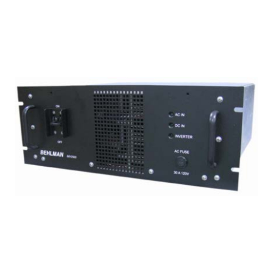
BEHLMAN MODEL INV 2500
FOR SERVICE ASSISTANCE
CONTACT BEHLMAN
CUSTOMER SERVICE DEPARTMENT
PHONE TOLL FREE 1-800-874-6727
OR WRITE
BEHLMAN
CUSTOMER SERVICE DEPARTMENT
80 CABOT COURT
HAUPPAUGE, NY 11788
PHONE: (631) 435-0435
FAX
: (631) 951-4341
FOR SALES INFORMATION:
PHONE: (631) 435-0435
USA
: (800) 874-6727
FAX
: (631) 951-4341
DATE:01/13
0
REV. 1
Advertisement
Table of Contents

Related Manuals for BEHLMAN INV 2500

Summary of Contents for BEHLMAN INV 2500
- Page 1 USER'S GUIDE AND TECHNICAL REFERENCE DC TO AC INVERTER BEHLMAN MODEL INV 2500 FOR SERVICE ASSISTANCE CONTACT BEHLMAN CUSTOMER SERVICE DEPARTMENT PHONE TOLL FREE 1-800-874-6727 OR WRITE BEHLMAN CUSTOMER SERVICE DEPARTMENT 80 CABOT COURT HAUPPAUGE, NY 11788 PHONE: (631) 435-0435...
- Page 2 DO NOT SUBSTITUTE PARTS OR MODIFY EQUIPMENT Because of the danger of introducing additional hazards, do not install substitute parts or perform any unauthorized modification to this equipment. Contact Behlman Electronics for proper replacement parts and specific service information. DANGEROUS PROCEDURE WARNINGS Warnings will precede potentially dangerous procedures in this manual.
- Page 3 File a claim with the freight carrier if the equipment has been damaged in any way or it fails to operate properly. Forward a copy of the damage claim report to Behlman. Include the model number, serial number and date the shipment was received. Behlman will advise the disposition of the equipment and will arrange for necessary repair or replacement.
- Page 4 Behlman shall be excused from supplying warranty service if the unit’s case has been open or if the unit has been subject to unauthorized repair. All service outside the scope of this warranty shall be paid for by the Purchaser at Behlman’s rates in effect at the time of this repair.
-
Page 5: Table Of Contents
TECHNICAL REFERENCE MODEL SERIES INV2500 DC TO AC INVERTERS TABLE OF CONTENTS INTRODUCTION Specifications INSTALLATION General Wiring Optional Alarm Contacts Optional Step-up Transformer OPERATING INSTRUCTIONS Controls and Indicators Optional alarm contacts Operational Considerations: Load Limitations Powering Reactive Loads Powering Lamps Powering Motors Powering Non-Linear Loads TROUBLESHOOTING... -
Page 6: Introduction
GENERAL INFORMATION INTRODUCTION The Behlman INV 2500 series of DC to AC power inverters incorporate the latest in switched mode power technology to provide regulated AC power from a user supplied DC source. These devices produce a sinewave output comparable to that which is available from typical utility power. -
Page 7: Installation
INSTALLATION AND OPERATION OF THIS DEVICE MAY EXPOSE HAZARDOUS VOLTAGES. REFER TO QUALIFIED PERSONNEL ONLY. The INV 2500 series inverters are designed to be installed in a standard 19" relay rack or EIA type enclosure. The front panel has a set of “ears” provided for this purpose. - Page 8 See section three of this manual for more information. CAUTION FAILURE TO OBSERVE DC POLARITY ON THE INPUT TO THIS DEVICE MAY CAUSE DAMAGE TO INTERNAL CIRCUITRY. THIS WILL VOID EQUIPMENT WARRANTY FIGURE 2-1 INV 2500 SERIES MANUAL REV 1 1/13...
- Page 9 AC INPUT \ OUTPUT WIRING 2500-48-XX # 6 AWG ( 60 A) # 10 AWG ( 25 A max.) 2500-125-XX # 10 AWG (23 A typ.) # 10 AWG ( 25 A max ) Table 2-1 INV 2500 SERIES MANUAL REV 1 1/13...
-
Page 10: Optional Alarm Contacts
. With this option a second rack mountable chassis is provided to convert the standard 120V output to the higher value. In addition, the bypass option can also be included with the external transformer. INV 2500 SERIES MANUAL REV 1 1/13... - Page 11 2-4. Special units may vary and will be identified by a four digit engineering code. Interconnecting wiring should be rated at 250Vac or better. Ring lugs are recommended for all connections. Figure 2-4 External Step-up transformer block diagrams INV 2500 SERIES MANUAL REV 1 1/13...
-
Page 12: Controls And Indicators
The table above lists the most common configurations for this model series. It should be noted that Behlman has produced many modified or semi-custom version of this model. This will be indicated by a four digit engineering code number appearing at the end of the model number. - Page 13 SECTION 3 OPERATION CONTROLS AND INDICATORS FIGURE 3-1 FIGURE 3-2 INV 2500 SERIES MANUAL REV 1 1/13...
-
Page 14: Operational Considerations
RMS value of 25 amps. This high peak current capability allows the INV 2500 series to start most high in - rush loads in it’s power range. It must be understood that the DC power source suppling the inverter must also have this capability in order to derive these benefits. -
Page 15: Powering Lamps
It should be noted that this type of load may cause the output waveform to exhibit “flat topping” This should not be associated with a defect of the inverter. Most “real world” electric distribution systems exhibit this distortion for this reason. INV 2500 SERIES MANUAL REV 1 1/13... - Page 16 This may show up as ringing or clipping. Ringing can be reduced by adding a small resistive “ pre-load” of about 10 to 20 watts across the output terminals. FIGURE 3-3 INV 2500 SERIES MANUAL REV 1 1/13...
-
Page 17: Theory Of Operation
TROUBLE SHOOTING THEORY OF OPERATION The INV 2500 series utilizes high frequency, switched mode, power conversion to convert the incoming DC to an AC output. The first stage is a DC to DC converter which “steps - up” the input voltage to a regulated +/- 200 Vdc. This voltage is applied to a second high frequency “housekeeping”... -
Page 18: Maintenance
! MAINTENANCE The INV 2500 series requires very little in the way of routine maintenance. If the unit is operated in a dirty or dusty environment it should be removed from service periodically and cleaned. The use of forced air is perfect for cleaning dust and debris from fan intakes and heat sink assemblies. -
Page 19: Mechanical Outline
MECHANICAL OUTLINE INV 2500 SERIES MANUAL REV 1 1/13...