Table of Contents
Advertisement
Quick Links
Preface
This instruction book briefly introduces the structure, performance, operation, and maintenance of
the 957H-type loader, as a reference for drivers, maintenance personnel and relevant technical
management personnel.
As to detail instruction for mating power, please refer to the instruction book of the diesel
manufacturer.
957H type wheel load are continuously improved. Individual content in this instruction may be
slightly different with delivered product; the customer is kindly advised to pay attention to during
application. In case spare parts are necessary for order, please write drawing number, name and
quantity clearly according to parts category and inform ex-work number, ex-work year and month,
type of engine of whole machine order to avoid delivering parts by mistake and affecting
maintenance work of customer.
We truly hope users will propose your opinions to the errors and shortages of this instruction book,
and to the quality of our products, and inform us at any time, so that we can further improve our
products and better serve our uses.
This product measures are up to the Q/CHL01.015-2012 standards wheel loader.
Changlin Company Ltd.
Changlin Company Limited
Add: No.898 West Huang He Road, Xinbei District, Changzhou City, Jiangsu Province
Zip:213136
Website: www.changlin.com.cn
Rest Day: Saturday and Sunday
Customer Service Hotline:4008600710
After-sales service:
Tel: 0519-86781012 86760000(domestic)
Fax: 0159-86751597(domestic)
Tel: 0086-519-86781288 0086-519-86752400(export)
Fax: 0086-519-86781537(export)
Supplier of the Company's Accessories:
Tel: 0519-86781017 86753324 86754849 86755924(domestic)
Fax: 0519-86752938(domestic)
Tel: 0086-519-86781535(export)
Fax: 0086-519-86781533(export)
Advertisement
Table of Contents

Summary of Contents for Changlin Company 957H
- Page 1 As to detail instruction for mating power, please refer to the instruction book of the diesel manufacturer. 957H type wheel load are continuously improved. Individual content in this instruction may be slightly different with delivered product; the customer is kindly advised to pay attention to during application.
- Page 2 Changlin Co., Ltd Environmental Protection Initiatives Dear users, Thank you for the Changlin products. Changlin Company Ltd. has passed through the ISO14001 Environment Management System Authentication on June 7, 2002. Changlin Company Ltd. became the first green manufacturing enterprise passing through the authentication in the China construction machinery industry. In...
-
Page 3: Table Of Contents
Content Fig. 0-1 Diagram of 957H Transmission System ....................1 Fig. 0-2 957H Overall Size of Loader with bucket ..................... 2 Application and Characteristics ......................... 3 Main Technical Performance and Parameters ..................4 III. Operating Devices and Meters........................8 Operation of Loader ..........................15 Safety Operation Rule:........................ - Page 4 Fig. 0-1 Diagram of 957H Transmission System...
- Page 5 Fig. 0-2 957H Overall Size of Loader with bucket...
-
Page 6: Application And Characteristics
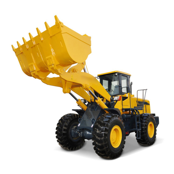
I. Application and Characteristics Application: Model 957H Loader is a kind of middle-and-large-sized, multi-purposed and high efficient engineering machinery equipped with operating units, such as grab, bucket, fork, etc. It is widely applied for loading and unloading log, shoveling, loading and unloading sand, earth, coal and short-distance transportation in construction engineering, road construction and road maintenance and repair, and the operations such as earth moving, land leveling, craning, traction, etc. -
Page 7: Main Technical Performance And Parameters
II. Main Technical Performance and Parameters Technical Performance Rated loading capacity Rated bucket cubic content 2.2-4.5 m 350mm Minimum claming diameter of grab (general grab) Maximum loading height: Grab (slope angle 46 3063 mm Bucket (slope angle 45 3100 mm Loading distance at maximum loading height: Grab 1433 mm... - Page 8 24V starting 24V starting Weight (kg) Note: 957H may select other engine on basis of performance guarantee of whole machine according to requirements of different areas and different customers, the customer is kindly advised to refer to engine instruction with machine.
- Page 9 Brake gas pressure 0.6 ~ 0.75 MPa Hand Brake Type Pneumatic internal expansion shoe type Steering System Model 957H Type Hinged frame, loading sensor, full-hydraulic steering Hydraulic steering gear displacement 1000 ml/r JHP2080S(C6121) ,CBGj2080/2040-XF(CUMMINS) Model of steering pump 2 - 90...
- Page 10 Refueling Capacity Crankshaft box of engine 20L(( 42L(C6121) CUMMINS Fuel chamber 250L Hydraulic torque converter and gear box Hydraulic oil tank 180L Front and rear axle driving 2 ×18L Hub reduction gear 4 × 3.0L Brake system 4 × 1.5L 10.
-
Page 11: Operating Devices And Meters
III. Operating Devices and Meters Before driving, it is necessary to know the location and function of each operating device, meter and indicating light. The arrangement of devices and meters in cab is shown in Fig. 3 - 1. The operator falls into the habit of watching the instrument board always in operation and discovers any abnormal condition on time. - Page 12 Instrument and indication lamp: Function and application scope of each instrument are listed as following: (1) Voltmeter Indicate voltage of system. Power supply voltage which is input into instrument is used to display system voltage, indication scope: 16~36Vdc. (2) Hour meter: Indicate accumulated working times of engine.
- Page 13 (7) Fuel level meter Indicate fuel oil level. Display through inspection of resistance value of fuel sensor placed in fuel tank. Total rotation angle of needle is 270°, stepping angle is 2°, indication scope: 0(E)~ 1(F); ≤1/8 is red zone, >1/8 is white zone. Indication lamp and switch: (1) Charging indication lamp If the indication lamp is lit, it means charging the battery.
- Page 14 (9) Emergency brake indication lamp: Standby. (10) Low brake pressure indication lamp: When this indication lamp is lit, it means brake air pressure is lower than 0.45MPa, don’t travel and operate. When this indication lamp isn’t lit, it means brake air pressure rise up 0.45MPa, then travel and carry out operation.
- Page 15 When the switch is pushed down, the top working lamp in the driving cab lights. Instrument lamp Switch When the switch is pushed down, all instrument lamps as well as front and rear width lamps light. Fan Switch When the switch is in middle position, fan will run in low speed.
- Page 16 (18) Safety pipe case When the fuse is replaced, the type shall be same as that of original fuse (it isn’t indicated in figure 3.1-1). (19) Air-condition system: The cab is equipped with air-condition system. When strong cooling is required, the switch of the air conditioner shall be turn to cooling position, the cooling degree can be suitably adjusted.
- Page 17 (5) Control lever of operating device: Bucket control lever. Rearward: If the lever is push to the left from neutral position, it will rest at this place till the bucket reach to the position that is set in advance, then the lever reverts the neutral position.
-
Page 18: Operation Of Loader
IV. Operation of Loader Safety Operation Rule: It is not permitted for unqualified driver to drive the loader. The driving trainee drives the loader under the instruction of the qualified driver. Before driving, the driver should understand the performance, structural characteristics, operation essentials and maintenance and service method as well as the necessary traffic regulations. -
Page 19: (Ii) Term Of Trial Operation
storage battery and parts from damaging. The fuel or oil suitable for winter weather should be used. 21. All damages resulting from operating, driving and maintenance and service not conforming to these operation regulations shall not be covered in “Three Guarantees – guaranteed repairs, guaranteed returns, and guaranteed exchanges that factories apply to their products in order to gain the trust of customers.”... -
Page 20: (Iii) Driving Of Loader
(3) Make maintenance and service at regular interval in and after the trial operation term. (4) Clean filter in hydraulic oil tank, rough filter in transmission system and air clearer. (5) Replace engine oil and hydraulic torque converter oil. ⅳ. 75% Rated Load Trial Operation Term (50 hours) (1) After 50% rated load trial operation term and check that all are normal, the loading is increased to 75% and revolution to 2200 rpm. - Page 21 The following items shall be check before starting: (1) Check that each meter indicates normally and engine charges. (2) Check that the sound of engine is normal in low speed or middle speed operation. (3) Check that the electric units, such as steering indicator light, braking light and horn, are normal. (4) Turn the steering wheel and check the reliability and tightness in steering system.
- Page 22 Third Gear – for running on good road without load. (4) Shift the gearshift handle in Forward and Backward (5) Loose the hand brake. (6) Horn, depress the throttle pedal and increase the revolution of engine to start up. iv. Shifting Gear: (1) The loader is equipped with torque converter, which is used for controlling the throttle in stepless speed change and can decrease the speed automatically in slope road with increasing driving force, so it is unnecessary to shift the gear.
- Page 23 ⅶ. Operations of the Loader Because working scope and operation object of the loader are very extensive, the instruction can’t describe in detail, many experience shall be obtained from practical operation by the driving personnel. Hereby only some common samples are listed for information. a.
- Page 24 When conjugate shovel run method is applied, its operation capacity is generally 1/2~1/3 of single shovel run method, the shovel is easily fully loaded. But the requirement on the operation level of the driver is higher, which is applicable to shovel load mine ore and uneven block materials. Fig.
- Page 25 In order to ensure normal application of the machinery, please be sure to implement according to above regulations! Other operations Handling, lifting and traction for short distance and shovel soil and levelling on loose floor etc operation can refer to above various operations. ☆...
-
Page 26: Lubrication
V. Lubrication The correct lubrication can reduce the frictional resistance between parts and wear-and-tear of parts to ensure the operation performance and lengthen the service life for loader. The oil in hydraulic transmission and hydraulic system simultaneously is used as lubricant and cooling oil. It is very important for feeding and replacing oil at regular interval to make the loader operate normally. - Page 27 Fig. 5-2 Lubrication and Feeding Location...
- Page 28 Table V – 1 Lubricant Feeding Periodic Chart Lubricating period Series Kind of Lubricating No. in Location of Lubrication Fig. ○ ⊙ Crank shaft chamber Fuel injection pump Diesel engine oil Governor Water pump & fan bearing Lubricating grease ...
- Page 29 List of Oil and Water used for Loader Season New standard oils and fluids Ambient Type Remarks temperature ℃ Standard code Oil trademark climate Extreme -29~0/-44~0 cold GB252-2000 Fuel Fuel tank Winter -14~10/-5~10 *-10 Light diesel Summer 4~40/12~40 Engines of Extreme vehicles -40~40...
- Page 30 the time. The increased debris may come from: the products from component oxidization and wear, the residues from combustion in the cylinder and the ingress of dust. When the content of these debris reaches 0.4~0.5%, the oil will become black in color and its physical and chemical properties will deteriorate. The oil should be changed when the engine is warm.
-
Page 31: Interval Technical Maintenance
VI. Interval Technical Maintenance Under the general operation condition, the interval technical maintenance has six terms – daily (8 – 10 hours), weekly (about 50 hours), monthly (about 200 hours), every season maintenance (about 600 hours), Semiannually (about 1200 hours) and annually (about 2400 hours) or maintenance and service can be made by customers according to the detailed operation and actual situation. -
Page 32: (Iv) Every Season Technical Maintenance
8. ▲After 150-hour operation, check the piston and seal cup ring of brake pump. If there are any mechanical damages or scale in seal ring lip, they are replaced. Technical (IV) Every Season Maintenance The following items are checked except daily maintenance, weekly maintenance and monthly maintenance: 1. -
Page 33: Structure, Adjustment And Maintenance Of Main Components
VII. Structure, Adjustment and Maintenance of Main Components Engine System: The power system supporting the loader comes from different company. The detail maintenance and troubleshooting of engine refer to the Operation Instruction of Engine. (II) Hydraulic Torque Converter and its Hydraulic Circuit System Structure and Function Fig. - Page 34 circulation hydraulic circuit. The power from engine is transmitted to pump wheel passing through geared ring and pump housing. When the operating hydraulic flows into pump wheel, it flows out along impeller vanes of pump wheel as the pump wheel rotate with centrifugation, flowing from the outlet of pump wheel to worm gear, shocking the worm gear vane, rotating the worm gear, bringing the worm shaft to rotate and transmitting the dynamic force.
-
Page 35: (Iii) Transmission
1. gearbox 2. compensating oil pump 3. fine filter 4. oil-in valve 5. torque converter 6. return valve 7. radiator 8. oil thermometer Maintenance and Service: (1) Often check the oil dipstick of gearbox to ensure the oil level is above the lowest scale. Add and replace oil strictly according to the stipulated oil. - Page 36 Fig.7-7 Structural Diagram of Gearbox 1. gearbox body 2. forward and backward gear assembly 3. reverse shaft 4. immediate shaft assembly 5. first-gear assembly 6. second- gear and third-gear assembly 7. output shaft assembly 8. gearbox cover...
- Page 37 Fig. 7-8 Schematic Diagram of Torque Converter and Gearbox Power Transmission Process of Gearbox: The gearbox can control the speed of loader in three speeds for forward and three speeds for backward. The power transmission process is shown as follows (See Fig. 0 - 1 Transmission System Diagram): Forward: I-Gear: gearbox input shaft forward clutch-on F ...
- Page 38 Structure and Principle of Hydraulic Clutch: Fig. 7-9 Hydraulic Gearshift Clutch 1. gear 2. driving friction disk 3. driven friction disk 4. piston 5. gear ring 6. cylinder block 7. spring 8. shaft 9. gearwheel 10. bearing cover 11. wave spring There are five hydraulic gearshift clutches with the same structure in gearbox (See Fig.
- Page 39 with 1.47 – 1.86 Mpa (15 – 19 kg/cm ) from oil-in valve of torque converter enters into the distribution valve, which plays the role of flow-control and pressure regulation (See Fig. 7 – 10). The gearshift valve is composed of valve body, direction control valve stem, gearshift valve stem, braking relief valve stem, air intake connection cover (See Fig.
- Page 40 Fig. 7-11 Gearshift Valve 1. valve body 2. gearshift valve stem 3. direction valve stem 4. braking relief valve stem 5. manometer joint 6. washer 7. braking lever connection sleeve 8. limit sleeve 9. braking lever return spring 10. washer 11.
- Page 41 Fig. 7–12 Drive Axle 1. axle housing 2. regulating nut 3. bracket 4. differential 5. regulating shim 6. bearing block 7. pressure cover 8. driving spiral bevel gear 9. bull flange 10. bull spiral bevel gear 11. thrust bolt 12. semi-axle 13. hub support shaft 14.
-
Page 42: (Iv) Drive Axle
(IV) Drive Axle The power from the gearbox shall be transmitted to the front and rear axles to drive the loader wheels by front and rear transmission cardan axle. The special-purposed engineering key transmission shaft is used for the front transmission shaft and rear transmission shaft. -
Page 43: (V) Steering System
The left and right turn of wheel loader are controlled by the steering system, which ensures that the driver can drive the loader in straight or in turn. Model 957H loader is equipped with full-hydraulic steering system consisting of hydraulic steering gear and priority valve. It has following advantages: (1) According to the requirements of steering oil circuit, no matter what the load pressure and revolution of steering wheel, the adequate oil supply can be ensured by the priority valve, which makes the steering stable. - Page 44 Fig. 7-13 Model 957H Steering System Layout Drawing 1. steering cylinder 2. TLF1-E1000B steering gear 3. priority valve 4. steering pump 5. cooler Operation Principle and Structure: Figure 7 -14 is hydraulic oil circuit figure of steering system, the priority valve 2 in figure and TLF1-E1000B wholly hydraulic steering gear consists of amplified hydraulic steering system, which can realize sensitive and stable steering, operation saves effort and efficiency of system is high.
- Page 45 Fig. 7– 14 Oil Circuit Drawing of Model 957H Hydraulic Steering System 1. oil pump 2. priority valve 3. one-way overflow valve block 4. TLF1-E1000Bsteering gear 5. steering cylinder 6. cooler 7.oil tank...
- Page 46 Fig. 7–16 Basic Layout Drawing of Model 957H Steering System 1. Pipeline between left and right oil cylinders 2. Pipeline between left and right oil cylinders 3. Control oil pipe 4. Pipeline between B port and oil cylinder 5.
- Page 47 Fig. 7–17 Model YXL-F250L-N7 Priority Valve 1. Safety valve assembly 2. Control spring 3.valve core 5. valve block 6.plug (4) Steering cylinder: cylinder diameterφ90mm, rod diameterφ45mm min. installation size: 770mm, max. installation size: 1205mm, stroke: 435mm. The structure is shown in Fig. 7 –...
-
Page 48: (Vi) Brake System
Fig. 7–18 Model 957H Steering Cylinder baffle 2. knuckle-joint bearing 3. anti-dust ring 4. baffle 5. baffle 6. O-ring 7. key 8. O-ring 9. sealing ring 10. guide shell 11. cylinder block 12. piston rod 13. sealing ring 14. guide ring 15. O-ring 16. piston 17. nut 18. splint pin 19. shaft sleeve... - Page 49 Fig.7-19a Spring air case 1. spare air inlet 2. air inlet 3. piston 4. drum spring 5.handspike 6.dust prevention cover 7. bolt Fig.7-19b Drum brake 1. brake drum 2. flange 3. spring 4. screw 5. brake hoof 6. brake board 7.
- Page 50 Air compressor pump is installed at right side of engine. The engine drives the air compressor pump and makes the compressed air enter into the oil-water separator and into left and right air reservoir through the governor valve and check valve. The oil-water separator is used for removing the water and oil-dirty from the compressed air exhausted from air compressor pump.
- Page 51 Fig. 7-21 Dual-pipe Air Brake Valve 1. braking pedal 2. crown bar 3. anti-dust sleeve 4. valve 5. crown bar seat 6. balance spring 7. major piston 8. spring seat 9. piston rod 10. diaphragm 11. diaphragm clamp plate 12. valve lead 13. Release spring of valve lead 14. Crown bar 15. Minor piston 16. Piston rod 17. Valve lead Fig.
- Page 52 enters into the oil cylinder of primary and secondary grips, pushing the piston and top cup to make the brake block griping the brake disk rotating together with wheel in order for braking. A-A rotate Fig.7-23 Assembly of Brake 1. Clamp body 2. Nut 3. Pin shaft 4. Dust proof ring 5.
-
Page 53: (Vii) Operating Device And Its Hydraulic System
Model 957H Working Principle of Operating Device and Hydraulic System The proportional pilot control system is used in Model 957H loader. Its working principle is shown in Fig. 7 – 24. Fig. 7-24 Schematic Diagram – Model 957H Hydraulic Steering System... - Page 54 Pilot valve is composed of operating lever and boom lever. The bucket lever has three positions – front, neutral and rear and boom lever has four positions – lifting, neutral, lowering and floating. The positions for lifting, floating and rear are located with electromagnet. When control level is in neutral position, the slide valve is in the starting position, the inlet oil chamber is not passing through the return oil chamber, the control orifice is not passing through the return oil chamber and multiplex valve is in neutral.
- Page 55 of multiplex valve open, inlet port, oil return port and operating oil port are passing through. At this time, the piston rod of boom shall float freely under the action of external force. (4) Action of overload valve and slippage valve When the bucket meets the foreign striking load and other mechanisms interfere, the overload shall open, playing the protection action.
-
Page 56: (Viii) Electricity System
precipitated and filtered for 48 hours before feeding in oil tank. (2) The filter in oil tank shall be cleared for every month. (3) Depending on the actual situation, the related hydraulic parts shall be cleared for one year within one year. (4) When the steering hydraulic system and operating hydraulic system are maintained, the screw plug in the operating oil tank shall be loosened (See #3 in Fig. - Page 57 Fig. 7 – 27 Principle figure of electric system...
- Page 58 System Specification: Galvanic Battery (Accumulator Jar) The machine applies two groups of 115E41R type 12 volts batteries which are connected in series. Negative pole of first group of battery is connected to positive pole of second group of battery, the negative pole of second group of battery is grounded through switch of the power supply, the positive pole (i.e.
-
Page 59: (Ix) Air-Condition System
(IX) Air-condition system This machine (957H) is equipped with an air-conditioner system, the type is BKG08G and the structure is shown in Fig.7-28. There are both functions of cooling and heating in this system. The whole system consists of the compressor, the condenser, the fluid reservoir, the evaporator and the connecting lines, etc. - Page 60 Fig.7-28 Air-conditioner system 1. compressor 2.water pipe 3.fluid reservoir 4. condenser 5.evaporator 6.water inlet pipe 7.water outlet pipe Fig. 7-29 The function of refrigerating...
- Page 61 Maintenance and cautions: Don’t disassemble the air-conditioner system at will to prevent the cold-producing from leaking. Check the belt tension of the compressor periodically, the tension should be controlled about 11-15mm. Clean the dirt on the surface of the condenser periodically to avoid the refrigerating effect failed. When replacing parts, replenish the refrigerant with imported SUNISO5GS or No.25 made in China according to the table as follows.
-
Page 62: General Fault And Elimination
VIII. General Fault and Elimination Part Fault Feature Possible Reason Elimination Method 1. Electric power insufficiency 1. Charged. 2. Adapter of starting circuit broken off or poor 2. Examining the wiring is connected correctly contacted. and fixed; besides clear away the dust and grease dirty on the interface. - Page 63 Part Fault Feature Possible Reason Elimination Method 1. Continuously heavy load operation or long time and high speed running. 1. Unloaded temporarily or stopped to have a 2. Oil level of gear-box is too high or too rest. Oil temperature is low.
- Page 64 Part Fault Feature Possible Reason Elimination Method 1. The connection bolt and tighten 1. Tightening or replacing. nut of axles and swing frame become flexible or even fallen off. Off-sound. Back 2. Insufficient of lubricating 2. Adding lubricating grease. axles and causing friction.
- Page 65 Part Fault Feature Possible Reason Elimination Method 1. Because of piping air leakage or 1. Removing the air leakage reason. using brake continuously result in air pressure is too low. 2. Assistor diaphragm wears result 2. Replacing. in air leakage. 3.
- Page 66 Part Fault Feature Possible Reason Elimination Method 1. Adjusting pressure of relief 1. Adjusting rated pressure 17.6Mpa. valve is incorrect. 2. Gear pump wear 2. Replacing working oil pump. seriously inner leakage. 3. Oil filter of oil box is blocked. 3.
-
Page 67: Transportation And Storage
IX. Transportation and Storage Transportation Long distance transportation can by train, large scale lorry or ship. Except abidance by rule of the traffic department, the following works need to be done well: (1) The front and back of all wheels should be padded steady by triangle wood. Then locking the frame. In order to avoid rolling, the front and back of loader would better to be fixed by rope or iron wire. - Page 68 (IV) Lifting: 1. Before lifting, the front and back frame should be locked by the frame lock on the left. 2. While using rope or steel wire rope to lift through front and back rings, the rope should be set on the position of center of gravity to avoid the rope been damaged or relative part of loader been scraped.