Table of Contents
Advertisement
Advertisement
Table of Contents

Summary of Contents for SYMC BC360
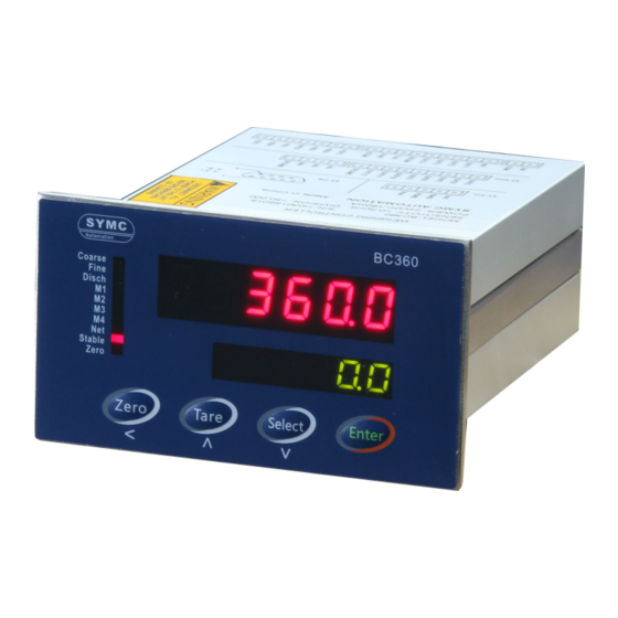
- Page 1 BC360 Electronic Weighing Indicator Technical/User Manual...
- Page 4 Contact us at: Shengyuan Measurement & Control Technology Co., Ltd. Add: No. 47, North Qingyang Road, Changzhou, JS, China Http:// www.symc-tech.net 201412 REV1.1...
- Page 5 Warning 1、this product is precision instrument, make sure the equipment is properly grounded before use. 2, only authorized person is allowed to debug, test and maintain system. Caution Observe precaution for handling electrostatic sensitive device.
-
Page 6: Table Of Contents
IRE CONNECTION 4.2.1 Power supply..........................5 4.2.2 Load cell connection........................5 4.2.3 series port........................... 5 4.2.4 Discrete input..........................6 4.2.5 BC360.A1 output control pins...................... 8 4.2.6 BC360.C1 output control pins...................... 8 4.2.7 Switch and jumper........................11 5 OPERATION............................12 5.1 D ............................12 ISPLAY 5.2 LFT S... - Page 7 13. DISCRETE IO TEST AND DEFINITION (F7)................48 13.1 D ........................48 ISCRETE INPUT TEST 13.2 D ........................ 48 ISCRETE OUTPUT TEST 13.3 D BC360.A1)............48 ( ISCRETE OUTPUT REDEFINITION ONLY FOR 14. FACTORY DEFAULT (F8).......................49 15. MAINTENANCES..........................50 15.1 ..........................50 EPAIR TOOLS 15.2...
-
Page 8: Attentions
Power supply: This terminal is powered by universal switch power. Rated power supply voltage 24~28VDC, current less than 200mA, Separate the power supply with any motor driven equipment. Environment: BC360 is not an intrinsic safe terminal and can not be used in hazardous area of explosive dust and gas directly. -
Page 9: Function & Features
Function & Features BC360 weighing indicator specially used for multiple ingredients batching during industry control. This terminal is a weighing control expert on packing scale, drum-filling scale, bulk weighing system, dosing and batching applications which widely suitable for such as metallurgy, chemical industry, construction material industry, painting, cereal &... -
Page 10: Technical Specification
Isolated RS232 or RS485 (Set by internal jumper) protocol Continuous output format, print output, MODBUS-RTU BC360.A1:four materials batching. Application modes BC360.C1/C2/C3:single material, two speed feeding control. Recipe Max 10 recipe records stored Power supply 20–28 VDC,<200mA Working temp: 10° ~ +40° C; humidity: 10% ~ 90%, non-condensing. -
Page 11: Installation And Connection
Installation and Connection Installation Front panel size(W x H):110mm X 62mm。 Enclosure size (W x H): 92mm x 45mm。 Cut out size:94mm X 48mm。 Diagram (unit: mm) : Wire connection Back plate connection drawing... -
Page 12: Power Supply
Negative power 4.2.2 Load cell connection BC360 is connected with max 6 pcs load cells of 350 ohms,(or load of 58 ohm). Wire connections as below. When connecting 4 wires load cell, jumper must be placed between +EXC and +SEN terminal and between EXC andSEN terminal. -
Page 13: Discrete Input
B/RX RS232 Rx,RS485 B- ICOM USART Common ground 4.2.4 Discrete input Indicator has 4 inputs(BC360.C1/C2/C3 only has one “RUN/STOP”). Input wire diagrams: COM2 Input definition under auto batching mode.(Parameters F6.6=0,F6.7=0) Input Definition Instruction Batching start Contact with DCOM over 100ms will trigger Auto-batching start command and stop after a batching cycle finished when disconnect with DCOM. - Page 14 Set IN1 ON to start a new batching cycle. No operation is enabled if IN4 keep contacted with DCOM2. Note: BC360.C1 has only one "RUN/STOP” Input, A 100ms-width pulse input will trigger a complete feeding and Dump cycle.
-
Page 15: Bc360.A1 Output Control Pins
4.2.5 BC360.A1 output control pins Output pin Function instruction Usage instruction OUT1 Redundant Isolation output with common ground connection. OUT2 Batch run status Each output max load is 30VDC/200mA。 OUT3 Redundant OUT4 Zero range OUT5 Material 1 feed(M1) OUT6 Material 2 feed(M2)... - Page 16 BC360.A1output pin logic connections Dump. Coarse Fine Material 4 N.W. Material 3 N.W. Material2 N.W. Materilal1N.W...
- Page 17 BC360.C1 output pin logic connections1---single material fixed data control ZTOL. Coarse Fine Dump Feed BC360.C1 output connection logic connections 2—fixed Dump material control Batching over signal:0.5 秒 Dump. Coarse Fine Dump...
-
Page 18: Switch And Jumper
4.2.7 Switch and jumper Main board mounts a switch SW2, Jumpers JP1 JP2, & JP3.: SW2-1 SW2-2 Normal operation Measurement of protection Internal testing Default Adjust JP1 and JP2, to configure RS232 or RS485interface: Adjust JP3 to set RS485 terminal resistance. Default is in OFF. -
Page 19: Operation
5 Operation 5.1 Display Power up sequence: 1、All LED segments light on for 2 seconds. 2 、 Upper display shows software number, lower display shows version number. for example, 1.5]. upper display shows [000292],lower display shows 3、enter into weighing display, if current load is under power-up zero range, the terminal execute power-up zero operation. -
Page 20: Lft Switch
Dump Dump Material 1 finished Material 1 is feeding Material 2 finished Material 2 is feeding Material 3 finished Material 3 is feeding Material 4 finished Material 4 is feeding Display Net weight Stab. Weight is Sable Weight is within zero tolerance. 5.2 LFT Switch Switch position... -
Page 21: Keypad
5.4 Keypad Keypad operation in gross display mode. Upper window display gross weight, lower window display “0”,Net cursor be off. Keypad Function Operation instruction Note The terminal executes tare operation under below conditions: 1) The terminal is in idle mode (no running procedure) 2) Keypad tare is enabled (parameter F2.2=1) 3) The weight signal is stable (cursor STAB. - Page 22 Keypad operation in menu mode The upper window displays menu index. Keypad Function Operation instruction Note Return to upper level or exit menu mode if in top Return menu. Select press “select” to change to every menu Press this key to edit the parameter or enter into Enter submenu.
-
Page 23: Batching Operation
5.5 Batching operation BC360 has two batching modes: mixed mode (F6.11=0) and recycle mode (F6.11=1) Mixed mode batching process Normally batching start by feeding each material one by one, then dump out. The whole cycle is named with five steps. And the whole cycle can be configured to work in 4 running modes. - Page 24 Recycle mode batching process In this batch mode terminal feeding then Dump each material one by one, batching process includes 4 steps. And the whole cycle can be configured to work in 4 running modes. Batching process Material 1 Material 2 Material 3 Material 4...
- Page 25 Menu list Instruction Required parameters FEED Enter into batching menu F6.6=1,F6.7=1 F3.1=1or 2,and one batching rEPort Print last batching report process cycle is finished. Print consumption list of output material (when printing finished, it reminds AccClr, asking if clear AccPrt F3.1=1or 2 total data.
- Page 26 FEED2 Target2 1 Select material order 2 Enter FEED3 Target3 1 Select material order 2 Enter FEED4 Target4 1 Select material order 2 Enter Disch actual Start discharging...
- Page 27 F3.1=2 Auto print report 1 Select batching report output 2 Enter Batching mode 2(semi-auto feeding / auto Dump) Display menu list Press [SELECT] key to select operating menu and press [ENTER] to execute selected menu command. Display list Instruction Required parameters FEED Enter into batching menu...
- Page 28 FEED1 Target1 1 Select material order 2 Enter FEED2 Target2 1 Select material order 2 Enter FEED3 Target3 1 Select material order 2 Enter FEED4 Target4 1 Select material order 2 Enter...
- Page 29 Disch actual F3.1=2 Auto print report 1 Select batching report output 2 Enter Batching mode 3(auto feeding / semi-auto Dump out) Press [SELECT] key to select operating menu and press [ENTER] to execute selected menu command. Display list Instruction Required parameters FEED Enter into batching menu...
- Page 30 Display list under batching suspended Display list Instruction Required parameters Continue un-finished work StoP Stop un-finished batching work Auto feeding / semi-auto Dump operation: FEED 1 Select feeding menu 2 Enter feeding menu disch actual Start discharging...
- Page 31 F3.1=2 Auto print report 1 Select batching report output 2 Enter Batching mode 4(auto feeding / auto Dump) Press [SELECT] key to select operating menu and press [ENTER] to execute selected menu command. Display list Instruction Required parameters Enter into batching menu F6.6=0,F6.7= 0 F3.1=1or 2,and one batching rEPort...
- Page 32 1 Select material order 2 Enter 1 Select feeding menu weight actual Auto discharging...
- Page 33 F3.1=2 Auto print report 1 Select batching report output 2 Enter Other instruction during batching process. noSHEt 1、If formula data (all data is zero), indicator shows “ ” when start. SHt.Err If formula data is wrong, indicator shows “ ”...
-
Page 34: Formula And Parameter Settings
6 Formula and parameter settings Keypad setting operation Keypad Function Operation instruction note 1)return to upper level if in menu navigation mode. 2)exit menu mode if in top menu. return 3 ) give up the modification and return in data edit mode. -
Page 35: Formula Parameter Setting [Setpt]
6.3 Formula parameter setting [SEtpt] Menu Instruction Operation instruction [M1] Material Lower window shows target value of material 1, press twinkle formula setting [ENTER] to edit the setpoints of material 1. Material At the beginning of material 1 feeding, the terminal first target target weight fast feeds weight to setpoint (... -
Page 36: Step By Step To Edit Setpoints Of A Specified Material
6.4 Step by step to edit setpoints of a specified material Step1: press and hold [ENTER] entering into menu tree. Step2: press [SELECT]=>[ENTER] scroll and enter into recipe menu step3: press [ENTER] entering into recipe edit mode. Press [TARE] key to select recipe number and [ENTER] to accept and store it. - Page 37 Step7: press [SELECT] in fine feed view mode or press [ENTER] in fine feed edit mode to navigate to preact setpoint view mode.In preact setpoint view mode press [ENTER] to enter into preact setpoint edit mode and the most left digit will blink. In preact edit mode, press [SELECT] to shift blink digit and press [TARE] to modify the digit value from 0~9.
-
Page 38: Weight Calibration Menu
Weight calibration menu Enter weight calibration menu Under normal weight display condition(not batching), press and hold [Enter] until the upper window shows top menu prompts. then press [SELECT] to scroll to “setup” prompt then press [ENTER] entering into scale and terminal submenu. Note: if the switch SW2-1 is switched to ON, all parameters in F1 group can be viewed but not modified except F1.4. -
Page 39: Input Calibration Parameter
Input Second This menu display only when F1.3 = 1. load inP L d 2 Input second load weight. To get better linearity result we weight suggest user add load weight as close as the full capacity. Put load weight on scale then press [ENTER] for calibration. Second add Lower window counts down from 10 seconds during Add L d 2... -
Page 40: Scale Application Parameter F2
3:MODBUS RTU 4: command format1 5: command format2 Check sum that parameter is invisible if F3.1 >0. F3.2 0:no check sum under BC360 continuous format 1:send check sun under BC360 continuous format F3.3 Baud rate 2400/4800/9600/19200 Data bits MODBUS RTU (parameterF3.1=3) , that parameter can F3.4... -
Page 41: Bc360 Continuous Output Format
0-99 ( Modbus communication node address should be F3.6 over 0) BC360 continuous output format That communication protocol require F3.1=0 。 BC360 send data string successively, it is composited with 17 or 18 bytes.。 data string sending frequency: baud rate 9600/19200: 20Hz; baud rate 2400/4800:10Hz Byte order instruction Initial character(=02H)... -
Page 42: Modbus Communication Protocol
Normal mode : tare weight Batching mode : Current material target weight if feeding Current batch total weight if dumping. Current material actual feed weight if paused. (ASCII code、without points) return character(=0DH) Check sum MODBUS communication protocol The terminal support MODBUS RTU multi-drop protocol. In MODBUS RTU network the terminal act as slave node and the registers can be accessed by reading hold register 03 command or writing hold register 06 command. - Page 43 .12 1: batch result over tolerance .13 1: in motion .14 0: auto feeding 1: Semi-auto feeding .15 0: auto dumping 1: Semi-auto Dump Actual batching data of current material 1(data is kept until next 40005 batching, and cleared when power off. Actual batching data of current material 2(data is kept until next 40006 batching, and cleared when power off.
- Page 44 40021 Spill to target of material 4 40022 Zero range (00~99 represent 0.0%F.S. ~9.9%F.S.) 40023 Auto spill correction frequency 40024 starting delay time 40025 Dump over output close delay time 40026 Comparison-inhabit time 40027 Checking delay time 40028 Read only(refer to last table) Numbers of finished batches.
- Page 45 No definition Batching start (F6.6=0) or continue batching Batching suspended Batching stop Dump(F6.7=1, and feeding is finished) Tare Clear tare Zero the scale Continue feeding or dumping 0001~1010 =1~10:choosing batching recipe No.(1~10) 40102 10:choosing semi-auto feeding mode(F6.6=1) 11:choosing auto feeding mode (F6.6=0) 10:choosing semi-auto Dump mode(F6.7=1)...
- Page 46 9.3 command format[F3.1 =4,F3.6 =0] The send command and response is ASCII format. The remote host send: The terminal response: Status Mode 7-byte weight with dp Unit Data field explaination Data field explaination status ST-data stable US-data is motion OL-weight out of range ,seperator mode NT-net weight...
-
Page 47: Enter ] Printing Format (F3.1=1 Or F3.1=2)
[Enter] printing format (F3.1=1 or F3.1=2) Under this communication protocol, pressing [Enter] will output following data:: F3.4=3 or 4: F3.4=0、1or 2(support Chinese) F3.5=1,print with units GROSS: 360.0 毛重: 600.5 GROSS: 600.5kg TARE: 180.0 皮重: TARE: 0.0kg NET: 180.0 净重: 600.5 NET: 600.5kg 9.5 Batching result printing format (F3.1=1or F3.1=2) -
Page 48: Option -- Analog Output Config (F4)
10. OPTION -- ANALOG OUTPUT CONFIG (F4) !The parameter group F4 is accessable only in the model BC360.C2 in which the analog output option board is installed. MENU parameter Description F4.1 0: gross weight Data map 1: display weight F4.2 Output mode 0:4~20mA output. -
Page 49: Option -- Proifbus Dp Config (F5)
You can download the latest GSD file from our website or contact with our support technician to get it. PROFIBUS parameter setup To configure the BC360 terminal for a PROFIBUS PCB, select F5 in setup, then select the following options. F5.1 Weight Data Type... -
Page 50: Data Definition
16 bit binary word (signed integer) numerical values. Each BC360 terminal represents a quarter rack of data to the PLC Option and each quarter rack provides two input (read) and two output (write) words. A quarter logical rack has 32 input bits (two 16 bit words) and 32 output bits (two 16 bit words). - Page 51 Select 3 Load Preset Tare Clear Tare Command Pushbutton Tare Comand Print Zero Reserved Reserved Cal Zero Cmd. Cal Span Cmd. Load Zero Tol. Load Fine Feed Load Spill value Load Target value Word0 is signed integer value, this value will be written into terminal according to bit 3 ~ bit 15 value in word 1.
- Page 52 0x0052 0x0011 0x0021 0x0051 0x0010 0x0020 0x0050 2、 A transition from 0 to 1 causes the value in Word 0 to be written into the preset tare register. 3、Bit4~bit7,bit 10, bit 11. A transition from 0 to 1 activates the command. 4、Bit12~15.
-
Page 53: Batching Function Parameter (F6)
Auto tare interval Range: 0~99. F6.5 0 = auto tare disabled. 1 ~99 = auto tare intervals F6.6 Feeding selection 0: automatic 1: semi-automatic (BC360.C1 only have 0) F6.7 Dump selection 0:automatic 1:semi-automatic F6.8 material 1/2/3/4 1~4 material optional(BC360.C1 only have 1)... - Page 54 When fast feed start or change from fast feed to slow feed, the suddenly material impact change will cause the scale signal bigger than the actual weight. To avoid capturing wrong weight data, the terminal do not read weight signal during the CIT time (F6.3.2). ...
-
Page 55: Discrete Io Test And Definition (F7)
‘1’:output active. Use multimeter shift to check the voltage between x and DCOM. 13.3 Discrete output redefinition(only for BC360.A1) In all 12 outputs only OUT1 and OUT3 are redundant outputs and can be redefined as any other port function. Menu Instruction Operation instruction F7.3... -
Page 56: Factory Default (F8)
F2.7=0; disable power up zero F3 parameter F3. 1=0; BC360 continuous protocols initialization F3. 2=0; BC360 no checksum bits F3. 3=2;9600 baud rate F3 Int F3. 4=0; 8 data bit / no checking bit F3. 5=0; manual print without unit F3. -
Page 57: Maintenances
All the total statistics data are cleared. F2、F3、F6、 Reset all the parameter groups. formula ALL Int parameter initialization 15. Maintenances 15.1 Repair tools. Millimeter sensor simulator, 2.5mm slotted screwdriver, Phillips screwdriver…etc. 15.2 Clearance Using soft cotton mixed with neutral detergent to clear indicator surface. Regularly asking professional maintenance staff to check and maintain. -
Page 58: Error And Reminding Lists
Sensitivity is too low to recognize. Increase load weight or input smaller value. Division ﹥50000 or ﹤500 Input weight =0 or ﹥ Capacity(F1.1) Load cell wiring inversed or no load is added on the scale. Linearity compensation range exceeds 20%, second calibration is invalid. - Page 59 SEtUP System calibration and setup rECiPE Edit recipe setpoints Calibration menu calibration F1.2 d Modify increments F1.1 C Edit the scale capacity E SCAL Zero calibration AddLd1 First load point calibration AddLd2 Second load point calibration inPLd1 Input first load weight inPLd2 Input second load weight Input calibration parameters...
- Page 60 Analog delicate adjusting on full scale. Initialize menu F2 int F2 group initialize F3 int F3 group initialize F6 int F6 group initialize SH int Recipe memory initialize Allint Initialize all menu parameters Recipe and setpoint edit menu rECiPE Recipe selection Edit setpoint SEtPt Edit preset batch quantity...
- Page 61 Packing list Please check following list content quantity note BC360 weighing controller BC360 manual M3 Sealing screws certificate...
- Page 62 ---------------------------------------------------- NOTE -----------------------------------------------------...
- Page 63 ---------------------------------------------------- NOTE -----------------------------------------------------...
Need help?
Do you have a question about the BC360 and is the answer not in the manual?
Questions and answers