Table of Contents
Advertisement
Quick Links
Advertisement
Table of Contents

Related Manuals for BanCon BC-B399

Summary of Contents for BanCon BC-B399
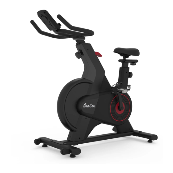
- Page 1 MAGNETIC BELT DRIVE INDOOR CYCLING BIKE BC-B399 w w w . o n e b a n c o n . c o m USER MANUAL IMPORTANT! Please retain owner’ s manual for maintenance and adjustment instructions. Your satisfaction is very important to us, PLEASE DO NOT RETURN...
-
Page 2: Table Of Contents
CONTENTS 1. IMPORTANT SAFETY INFORMATION 2. EXPLODED DIAGRAM 3. PARTS LIST 4. HARDWARE PACKAGE 5. ASSEMBLY INSTRUCTIONS 6. BATTERY INSTALLATION & REPLACEMENT 7. ADJUSTMENTS & USAGE GUIDE 8. MAINTENANCE INSTRUCTIONS 9. EXERCISE METER 10. SPECIFICATIONS... -
Page 3: Important Safety Information
IMPORTANT SAFETY INFORMATION We thank you for choosing our product. To ensure your safety and health, please use this equipment correctly. It is important to read this entire manual before assembling and using the equipment. Safe and effective use can only be achieved if the equipment is assembled, maintained, and used properly. It is your responsibility to ensure that all users of the equipment are informed of all warnings and precautions. -
Page 4: Exploded Diagram
EXPLODED DIAGRAM - 2 -... -
Page 5: Parts List
PARTS LIST Description Spec. Description Spec. Main Frame Flywheel Axle θ10*107*2-M10*1.0P Front Stabilizer Flywheel Spacer θ15*θ10.1*40.6 Rear Stabilizer Bushing Adjustable Bottom Upright 30*30*20 Handlebar Tube Cover Fixed Base Handlebar Top Upright Cover θ15*14 Fixed Base Adjustable Seat Tube Magnetic Snap-fit θ17*9 Seat Slider Base... - Page 6 Description Spec. Description Spec. Bolt Cap θ20.5*5 Black Hexagon Flange M10*1.25P*9H θ43*17-M8*20 Adjustment Foot Pad C-clip PU+Q235A Hexagon Nut M8*35 End Cap 80*45*48.7 Hexagon Lock Nut Console Hexagon Socket Nut M6*72 Console Wire 5PIN 450mm Hexagon Lock Nut Battery Cover 57*51.5*11.5 Flat Phillips Screw M6*10...
-
Page 7: Hardware Package
HARDWARE PACKAGE #Allen Wrench S5-S6 1PC #9 (NO. 63) M8*15 4PCS #8 (NO. 60) M8*55 4PCS #10 (NO. 61) θ8.4*θ16*t1.6 4PCS #11 (NO. 62) θ8.1*θ12.3*t2.1 8PCS #Spanner S13-S14-S15 1PC NOTE: #8 ( NO. 60) is number 8 in "HARDWARE PACKAGE" refers to number 60 in "PARTS LIST" and "EXPLOD- ED DIAGRAM". -
Page 8: Assembly Instructions
ASSEMBLY INSTRUCTIONS We value your experience using Bancon Health and Fitness products. For assistance with parts or trouble- shooting, please contact us at support@onebancon.com. NOTE: We recommend having 2 people to assemble the product. STEP 1 1. Place the box on 2 square meters of free space to assemble the equipment. - Page 9 STEP 3 #11 (NO. 62) # 9 (NO. 63) θ8.1*θ12.3 4PCS M8*15 4PCS Let the Communication Wire A from Main Frame (NO. 1) through Adjustable Handlebar #Allen Wrench 1PC Tube (NO. 4) by tying L-Shaped Wire. Loosen and pull out Adjustment Knob (NO. 20), insert Adjustable Handlebar Tube (NO.
- Page 10 STEP 4 Use Spanner to remove 4 Pan Phillips Bolts on the Console (NO. 54), the Bolts should be kept in good condition. Connect Communication Wire D from Console (NO. 54) with Communication Wire C on Handlebar (NO. 5), insert the connected wires into the Handlebar (NO. 5). Secure the Console (NO.
- Page 11 STEP 5 WARNING! Read instructions carefully as #Spanner 1PC improper assembly may cause permanent damage to your bike. NOTE: The Pedals (NO. 14L & NO. 14R) are marked “L” and “R” for Left and Right. Connect the Left & Right Pedal (NO. 14L & NO.
-
Page 12: Battery Installation & Replacement
BATTERY INSTALLATION & REPLACEMENT BATTERY INSTALLATION: Take out 2 AA batteries from the plastic bag for Battery Cover manual. 2. Press the buckle of Battery Cover (NO. 56) on the back of Console (NO. 54), then remove the Battery Battery Cover (NO. -
Page 13: Adjustments & Usage Guide
ADJUSTMENTS & USAGE GUIDE ADJUSTING THE BALANCE In order to achieve a smooth and comfortable ride, you must ensure that the stability of the bike is secured. If you notice that the bike is unbalanced during use, adjust the Adjust- ment Foot Pad (No. - Page 14 ADJUSTING THE SEAT CUSHION The seat of this bike is fully adjustable as it moves Up, Down, Fore (forward), Aft (backward). To adjust the height of Adjustable Seat Tube (NO. 6), loosen and pull the Adjustment Knob (NO. 20) outward, then raise or lower the seat to the desired height.
- Page 15 ADJUSTING THE HANDLEBAR It is important that the handlebar and seat are both set to the correct height to your body. To adjust the handlebar height, loosen and pull the Adjustment Knob (NO. 20) outward, then slide the Adjustable Handlebar Tube (NO. 4) up or down to the desired height.
-
Page 16: Maintenance Instructions
MAINTENANCE INSTRUCTIONS Read all maintenance instructions fully before you start any repair work. In some conditions, an assistant is required to do the necessary tasks. Daily Before each use, examine the exercise machine for loose, broken, damaged, or worn parts. Do not use if found in this condition. -
Page 17: Exercise Meter
EXERCISE METER FUNCTION BUTTON MODE: Press this button to changeover display or SCAN SPEED CALORIES LEVEL TIME DISTANCE choose function (SCAN, TIME, SPEED, DISTANCE, CALORIES, RPM, LEVEL). Hold it for 3 seconds to reset all the values. FUNCTIONS SCAN: Press MODE button until “SCAN” appear, meter will rotate through all the functions: SCAN, TIME, SPEED, DISTANCE, CALORIES, RPM, LEVEL. -
Page 18: Specifications
SPECIFICATIONS SCAN Every 6 seconds TIME 0:00 ~ 99:59 MIN:SEC SPEED 0 ~ 99.9 MPH DISTANCE 0 ~ 999.9 MILE FUNCTION CALORIES 0 ~ 9999 KCAL 0 ~ 999 R/MIN LEVEL 1 ~ 8 BATTERY TYPE 2 pcs of SIZE -AA OPERATING TEMPERATURE 0℃... - Page 19 W W W . O N E B A N C O N . C O M CONNECT WITH US FOR FITNESS ARTICLES, VIDEOS & WORKOUTS @BANCON @BANCONFITNESS @BANCONFITNESS @BANCONFITNESS @BANCONFITNESS...
- Page 20 This device complies with Part 15 of the FCC Rules. Operation is subject to the following two conditions: (1) this device may not cause harmful interference, and (2) this device must accept any interference received, including interference that may cause undesired operation NOTE: This equipment has been tested and found to comply with the limits for a Class B digital device, pursuant to Part 15 of the FCC Rules.