Advertisement
Quick Links
Advertisement

Related Manuals for Explore Science 88-90153

Summary of Contents for Explore Science 88-90153
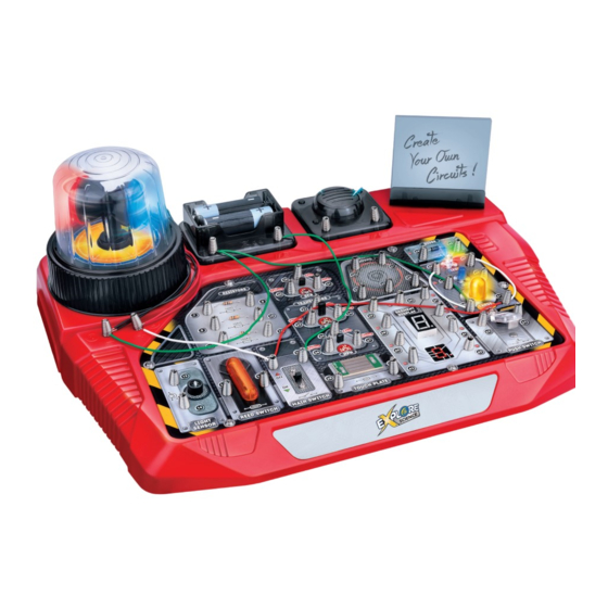
- Page 1 88-90153 ELECTRONIC EXPERIMENTS SET INSTRUCTIONS...
- Page 2 ELECTRONIC EXPERIMENTS SET We take pleasure to welcome you to try out this ready-to-use electronic circuit kit suitable for children of 8 years old and up. “You’ll be amazed” to nd what you can learn as the experiment is a realistic concept of electronics and electricity. It will de nitely enable you to learn about the necessary electronic components, circuits, and theories as well as the basic electronics principles –...
- Page 3 BASIC CIRCUIT SYMBOLS Component Circuit symbol Explanation A wire is like a path that allows electric current to ow through. It has very low Wire resistance which is close to zero. Battery Each symbol represents a battery. On/o switch The main switch. Press it to make the metal plates come into contact.
- Page 4 COMPONENTS IN THIS KIT Description Quantity Description Quantity Circuit Board Unit Alarm body (halved) 2pcs Magnetic pole Red & Blue cover 2pcs 10cm x 8pcs, 20cm x 5pcs, Gear Connecting wire 30cm x 5pcs Motor with a worm Instruction Manual Alarm base cover Memo holder base Transparent cover...
- Page 5 ANIMAL DIODE DIODE ANIMAL SOUND SOUND Gate RESISTORS RESISTORS Cathode Anode TRANSISTORS TRANSISTORS Base Emitter Collector 100K 100K SEGMENT SEGMENT DISPLAY DISPLAY Base LARGE LARGE Emitter Collector LIGHT LIGHT LIGHT SENSOR SENSOR REED SWITCH REED SWITCH MAIN SWITCH MAIN SWITCH TOUCH PLATE TOUCH PLATE PUSH SWITCH...
- Page 6 50+ EXPERIMENTS 1. Simple LED circuit 27. Digital segment LED switching between “1” and “8” 2. Spinning LED light 28. Digital segment LED switching between “I”, “L” , “F” and “E” 3. Function of the reed switch 29. Light control seven-segment LED display – C (Dark Type) 4.
- Page 7 EXPERIMENT EXPERIMENT Simple LED circuit Spinning LED light 4-2, 1-17, 18-3 4-51, 50-17, 18-3 Wiring Sequence Wiring Sequence • • Complete all wiring connections as indicated in the sequence. By switching Complete all wiring connections ON, the LED will light up. By switching OFF, the LED will extinguish. You can as indicated in the sequence.
- Page 8 EXPERIMENT EXPERIMENT A simple demonstration of a function of the PNP transistor A simple demonstration of the function of the NPN transistor 4-23, 24-49, 22-29, 28-48-17, 18-3 4-49-29, 28-25, 27-48, 26-17, 18-3 Wiring Sequence Wiring Sequence • • Complete all wiring connections as indicated in the sequence. Switch on the Complete all wiring connections as indicated in the sequence.
- Page 9 EXPERIMENT EXPERIMENT LEDs Combination Spinning LED light in advance circuit operation of LEDs Wiring Sequence 4-52-51, 50-16-48, 49-53-47, 46-15-17, 18-3 Wiring Sequence 4-17, 18-49-53-16, 15-48-51-8, 7-50-52-2, 1-3 • • Complete all wiring connections as indicated in the sequence. Switch on the Complete all wiring connections as main switch.
- Page 10 EXPERIMENT EXPERIMENT Demonstration of a simple function of SCR A practical example of SCR 21-50, 51-4-10, 9-53, 52-19, 20-17, 18-3 Wiring Sequence 21-50, 51-4-29, 28-19, 20-17, 18-3 Wiring Sequence • • Complete all wiring connections as indicated in the sequence. Switch on the Complete all wiring connections as indicated in the sequence.
- Page 11 EXPERIMENT EXPERIMENT Light control seven-segment LED display – C (Dark Type) Digital segment LED switching among “I”, “L” , “F” and “E” Wiring Sequence 3-18, 11-25-14, 4-36-12, 13-17-26-8, 7-41, Wiring Sequence 4-17, 18-7, 8-36, 35-40-15-3-52, 53-37-38, 27-35-37-40-42 42-16 • Complete all wiring connections as indicated in the sequence. Switch on the •...
- Page 12 EXPERIMENT EXPERIMENT Horse neighing sound and flashing digit “4” Bird chirping sound and flashing digit “5” 3-18, 4-36-33-34-6, 17-31, 3-18, 4-6-36-33, 17-31-34, Wiring Sequence Wiring Sequence 30-35-38-39-43-5 5-30-35-37-38-42-43 • • Complete all wiring connections as indicated in the sequence. By Complete all wiring connections as indicated in the sequence.
- Page 13 EXPERIMENT EXPERIMENT Magnet control sheep baaing sound with flashing LED Manual control horse neighing sound with push switch control flashing digit “0” Wiring Sequence 3-18, 17-24-31, 32-15, 16-7-30-22-48, 49-8-6-4, 5-23 3-18, 4-6-36-34-33, 5-30-52, 53-40-42-43-35-37-39, Wiring Sequence 41-7, 8-31-17 • Complete all wiring connections as indicated in the sequence. Switch on the main switch.
- Page 14 EXPERIMENT EXPERIMENT Water level LED alarm Light intensity indicator 3-18, 4-7-28-47, 17-48-12-26, 8-27-49-46, 3-18, 4-7-14-47, 17-12-26-48, 8-27-46-49, Wiring Sequence Wiring Sequence 11-29-25 11-13-25 • • Complete all wiring connections as indicated in the sequence. Switch on the Complete all wiring connections as indicated in the sequence. Switch on main switch.
- Page 15 GLOSSARY Battery – A source of energy. It contains chemicals which will undergo chemical reaction to produce electricity when a circuit is connected. Circuit – A system of interconnected components / devices such as power source, resistors, capacitors and transistors…etc. Diode –...
- Page 16 © 2021 Explore Scientific, LLC. 1010 S 48th Street, Springdale, AR 72762 explorescientificusa.com | 866.252.3811 All rights reserved. Made in China. If at any time in the future you should need to dispose of this product please note that waste electrical products should not be disposed of with household waste.
Need help?
Do you have a question about the 88-90153 and is the answer not in the manual?
Questions and answers