Advertisement
Quick Links
© 2021 The Swingset Company
INSTALLATION INSTRUCTIONS
Swing Extreme
Need a hand? Give us a call. 888.525.1185
Also, feedback is appreciated. If you think any part of this manual is
confusing, or if you have suggestions for how to better explain one of the
steps, please let us know by emailing info@theswingsetco.com
Section 1
The Swingset Company
1
Advertisement

Related Manuals for The Swingset Swing Extreme


Summary of Contents for The Swingset Swing Extreme
- Page 1 © 2021 The Swingset Company INSTALLATION INSTRUCTIONS Swing Extreme Need a hand? Give us a call. 888.525.1185 Also, feedback is appreciated. If you think any part of this manual is confusing, or if you have suggestions for how to better explain one of the steps, please let us know by emailing info@theswingsetco.com...
-
Page 2: Tools Needed
The Swingset Company (TSC) team has designed the easiest playset to assemble (in our humble opinion :) We’ve pre-drilled all the holes, sanded all the wood, and pre-assembled many of the parts for you. We even use the fewest variations of fasteners. We hope you find this assembly to be enjoyable and stress-free. But if you get stuck, don’t hesitate to call us at 888.525.1185. -
Page 3: Safety Instructions
The Swingset Company (TSC) shall not be liable for The maximum safe weight on the Fort deck is 500 lb. incidental, indirect or consequential damages or... - Page 4 “Fort Accessories”. This is where you’ll find all your screws and the special drill bit required for assembly. We’ve provided a few extra screws in each bag, just in case you lose a few J Section 1 The Swingset Company...
- Page 5 Crossbeam. Use the provided drill bit (T-25) to attach all the screws in this manual. [Tip: use a 90 degree angle to ensure the beams are square & perpendicular] Parts Needed: T-25 Figure A Section 1 The Swingset Company...
- Page 6 Make sure Parts Needed: the narrow support bars face this way Figure C Section 1 The Swingset Company...
- Page 7 IMPORTANT: The ground beneath each post must be at the same level to ensure all beams are horizontal and square. Parts Needed: Make sure all beams are flush to the edges of the posts, as shown. Figure D Section 1 The Swingset Company...
- Page 8 Figure E. Tip: Make sure the end of each Brace lines up with the edge of each Post and the bottom of the beam, see figure F. Figure F Parts Needed: Figure E Section 1 The Swingset Company...
- Page 9 You’ll need your friend again for this step. Insert the two Deck Floors. They are identical. The cutout in the floor joists should rest on the support bars of the Crossbeams. Do NOT screw them into place yet. Parts Needed: Section 1 The Swingset Company...
- Page 10 Finally, attach the last two Crossbeams (#2) using the prior page in order to better demonstrate the two “A” screws in each side, See Figure H. upcoming steps. Parts Needed: For ladder, see separate instructions that came with this part. Section 1 The Swingset Company...
- Page 11 “C” screws, one on each end, as shown to the right. Finally, install the 2 green safety handles which came with the ladder. One handle will attach to the Post, the other to the Tall Vertical. Parts Needed: Section 1 The Swingset Company...
- Page 12 Step 8: Screw the Deck Floors in Place Now you can secure the deck floor using the 8 pocket holes under the deck floor. Use the “C” screws, as shown. Parts Needed: Section 1 The Swingset Company...
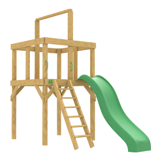
- Page 13 GREAT JOB! The Fort should look like this. Section 1 The Swingset Company...
- Page 14 SECTION 2: “Swing Extreme” SWINGSET Walls, Extension Beams & Other Attachments PREMIER by The Swingset Company...
- Page 15 Step 9: Attach Climbing Wall Attach Rock Climbing Wall. See separate instructions provided with rock climbing wall packaging. The Climbing Walls goes directly behind the ladder on the opposite side of the deck. “B” “B” “B” “B” “D” Parts Needed: “D”...
- Page 16 Wall must go all the way to edge of each post, Step 10: Attach Walls and to middle of the center vertical beam. Find the 5 walls and attach them as shown. Make sure to align the ends of each wall with the outside edges of the posts.
- Page 17 Step 11: Picnic Table The picnic table will go underneath the deck floor. Use the instruction sheet that came packaged with the Picnic Table for assembly. IMPORTANT: Make sure to place the picnic table on the same side of the fort that the swing beam will be connected to.
- Page 18 Step 12:Chalkboard Attach the chalkboard to the inside of 2 posts. Use the Instruction Sheet that came attached to the Chalkboard.
- Page 19 SECTION 3 The Swing Beam & A-Frame YOU WILL DO SECTION 3 TWO TIMES. ONE TIME FOR EACH SIDE OF THE FORT. Section 3 The Swingset Company...
- Page 20 Posts and Verticals, as shown. Push bracket down over the upper crossbeam so it fits snuggly into place. Secure the bracket using 3 "B" screws, as shown in Figure P . Figure P Parts Needed: Fort Bracket The Swingset Company Section 3...
- Page 21 IMPORTANT: Turn the Swing Beam upside down so that is NOT trimmed. down. the Swingset Company decal is upside down. The Swing Beam has one side that is trimmed and one side that is not. The A-Frame Bracket goes on the end of the Swing Beam that is NOT trimmed.
- Page 22 Step 4: Attach A-Frame Legs to Swing Beam Find the 2 legs (#7) of the A-Frame. Slide them into the A-Frame Bracket as shown. Install the 4-1/2" bolts, nuts & washers as shown, but don’t fully tighten until later. Parts Needed: Section 3 The Swingset Company...
- Page 23 A-Frame legs to achieve a perfectly level Swing Beam. Once the Swing Beam is in place and level, install 2 “B” screws in each side of the Fort Bracket, as shown in Figure V. Parts Needed: Section 3 The Swingset Company...
- Page 24 Support Bracket. Finally, fully tighten the Bolts in the A-Frame Bracket. Figure X 1 “A” Screw on each side of beam Parts Needed: Figure W Legs must be AT LEAST 7ft apart. No Less. Section 3 The Swingset Company...
- Page 25 The first completed side of the swing beam & A-frame assembly. NOW YOU GET TO DO IT AGAIN FOR THE OPPOSITE SIDE. REPEAT SECTION 3, THIS TIME ON THE OTHER SIDE OF THE FORT. Section 3 The Swingset Company...
- Page 26 While a helper holds the opposite side in one corner, pull the tarp tight. Adjust as needed to keep the sides even. Secure to upper beams with one “B” screw per grommet hole. Repeat until all grommets are secured Parts Needed: Section 3 The Swingset Company...
- Page 27 For the telescope, use the provided yellow “L” brackets to hold down the telescope base onto the crossbeam. YOUR SWINGSET IS COMPLETE! (oh, we provided extra screws, so don’t worry if you still have a few screws leftover J ) The Swingset Company...
-
Page 28: Layout Diagram
FRONT the layout, be sure to evaluate the safety of your changes. SWING EXTREME Overall dimensions: Front to back:17 ft. Left to right:25 ft. Layout Diagram 3645 Clearview Parkw ay ASTM Standard recommends the area around the...
Need help?
Do you have a question about the Swing Extreme and is the answer not in the manual?
Questions and answers