Advertisement
Quick Links
Multiplex Echo Machine
The Multiplex Echo Machine is based on tape delays of the past. It has selectable
"modes" that recreate a good approximation of the delay's they emulate. It also
includes a control for on the fly tape speed manipulation, allowing the repeats to
speed up or slow down while pressing and releasing the footswitch.
What to expect...
This is not a pristine digital delay, some noise will be experienced. Even tape
delays have noise, it just adds to the character...
©2016 JRM/1776effects
www.1776effects.com
1
Advertisement

Summary of Contents for JRM/1776effects Multiplex Echo Machine
- Page 1 Multiplex Echo Machine The Multiplex Echo Machine is based on tape delays of the past. It has selectable “modes” that recreate a good approximation of the delay’s they emulate. It also includes a control for on the fly tape speed manipulation, allowing the repeats to speed up or slow down while pressing and releasing the footswitch.
- Page 2 1776 TIP: For ultra LoFi fun set both delay pots to max delay time with the feedback set at one repeat. While playing hold and release the tape speed switch. This will create a detuned looping type chaos! FeedBack Signal In Signal In Signal Out Delay 1 Delay 2 Binson Mode ©2016 JRM/1776effects www.1776effects.com...
- Page 3 1776 TIP: With a medium delay time hold the tape speed switch until the LED is fully lit. Play and then release the footswitch for a “dive bomb” type effect. Then quickly step on the switch again for more musical detune action. Signal In FeedBack Signal Out Delay 1 Delay 2 EP-3 Mode ©2016 JRM/1776effects www.1776effects.com...
- Page 4 1 uF 100n 1 uF Diodes 1n4001 1n4001 Potentiometers 1 uF DELAY1 50kB 10uF DELAY2 50kB Tant 1 uF 50kB 50kB Trimmer V-ADJ *socketing recommended for experimentation! **USE 1M for R31 and 33k for R33 with black H11F1 ©2016 JRM/1776effects www.1776effects.com...
- Page 5 PT2399’s out of your batch use them in IC2 and IC3. Even with the best PT2399’s you will experience some noise at certain settings of delay time and/or repeats. You can increase the filtering but the delay will sound more analog then tape. ©2016 JRM/1776effects www.1776effects.com...
- Page 6 One: Take the PCB and place it component side down. Two: Size and cut a piece of cardboard to slip under the pots. Three: Place the potentiometers in the correct locations. It will look like the picture... ©2016 JRM/1776effects www.1776effects.com...
- Page 7 Four: Solder in place, like so... (It’s easiest to do the mix pot first) Five: Then solder the pot pins on the component side as well. ©2016 JRM/1776effects www.1776effects.com...
- Page 8 • Connect +9v and gnd to the PCB circuit • Put you multimeter on the DC V setting. • Take the black probe and place it on a ground point. • Take the red probe and place it on the cathode of D3. ©2016 JRM/1776effects www.1776effects.com...
- Page 9 Note: D2 is a visual indicator of the Tape Speed Mod, it is not an on/off indicator for the effect. It can be PCB mounted. Use the drill guide for proper enclosure drilling. An additional LED is necessary along with a CLR as shown in Madbean’s wiring diagram for effect on/off status. ©2016 JRM/1776effects www.1776effects.com...
-
Page 10: Additional Notes
Have fun, there are many cool sounds to be found! Last but not least, I owe a special thanks to Brian (aka Madbean) and all the crew on the forum. Without your support this project would have never happened! Josh ©2016 JRM/1776effects www.1776effects.com... - Page 11 ©2016 JRM/1776effects www.1776effects.com...
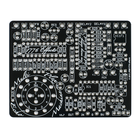
- Page 12 PCB Size 2.44” H x 3.06” W Delay 1 Delay 2 Feedback Binson RE-201 EP-3 Tape Speed This document and board layout is designed for personal use only! No commercial use without written authorization from the owner. ©2016 JRM/1776effects www.1776effects.com...
Need help?
Do you have a question about the Multiplex Echo Machine and is the answer not in the manual?
Questions and answers