Table of Contents
Advertisement
Quick Links
Advertisement
Chapters
Table of Contents

Summary of Contents for SCINTREX ENVI-MAG
- Page 1 Part Number 788 711 November, 1994...
- Page 2 SCINTREX Limited. ENVI-MAG, WALKMAG and ENVIMAP are trademarks of SCINTREX Limited. November, 1994 Manual designed and produced by GEO F/X.
-
Page 3: Table Of Contents
Table of Contents Preface Features ............... vii Upgrades and options ..........viii ENVIMAP software included ..........ix How to use this manual ..........ix HELP-Line ..............xi The ENVI-MAG Instrument Introduction Cold boot ..............A1-2 Instrument overview ..........A1-2 Preparing the ENVI-MAG Unpacking ..............A2-2 Repacking ..............A2-3 Assembly ..............A2-3... - Page 4 Table of Contents Setting-up the ENVI-MAG First time operation ..........A4-1 General setup principles ...........A4-4 How to: ..............A4-5 Line and Station setup ..........A4-7 Basic Mode ...............A4-9 Search Mode ............A4-11 Advanced Mode ............A4-12 Operating the ENVI-MAG Accurate and meaningful measurements ....A5-1 Repeated surveys lines ..........A5-4...
- Page 5 Reference information ENVI-MAG technical specifications ......A8-1 Instrument parts list ..........A8-4 Warranty & Repair ...........A8-5 Applications for the ENVI-MAG Magnetic surveying overview Introduction ..............B1-1 Basic magnetic theory ..........B1-1 Magnetic targets ...........B1-11 Survey planning Introduction ..............B2-1 Sampling intervals ............B2-1 Precision and Accuracy of surveys ......B2-3...
- Page 6 The ENVIMAP software ..........C1-1 Processing system steps .........C1-1 Conventions used in this section ......C1-2 Installation and getting started Before you begin ............C2-1 Installation procedure ..........C2-2 If you have problems ..........C2-13 ENVIMAP Reference Limitations ...............C3-2 Menuing system ............C3-2 Menu Reference ............C3-10 ENVI-MAG Manual...
-
Page 7: Features
Preface Preface Congratulations on purchasing the ENVI-MAG environmental magnetometer/ gradiometer from SCINTREX Ltd! You are in possession of one of the most advanced magnetometers for environmental, geotechnical, archaeological and mineral exploration uses of today. The ENVI-MAG is a portable, proton-precession magnetometer that also is inexpensive, lightweight and rugged. -
Page 8: Upgrades And Options
2. Base-station applications An accessory kit allows the sensor and staff to be converted into a base- station sensor and the cabling allows a field ENVI-MAG to be connected for automatic magnetic diurnal-variation corrections. 3. Low temperature operations An external battery pouch along with a thermostatically controlled display heater will permit field operations down to minus 40°C. -
Page 9: Envimap Software Included
ENVIMAP software included ENVIMAP software included The ENVIMAP software provided with your ENVI-MAG is an easy to use, user- friendly, menu-driven system. It will download your data from the ENVI-MAG and produce report quality contour maps of your survey on a variety of printers. A complete description of the software and its use can be found in the third section of this manual. - Page 10 You should pay special attention to this section. Indicates a warning. You should read this section very carefully. Indicates a typical question you may have and provides an answer. Please read this! Indicates a very important message. viii ENVI-MAG Manual...
-
Page 11: Help-Line
HELP-Line In order to provide a high-degree and quality of technical support, a special HELP-Line is available for ENVI-MAG users. If you need any help with the instrument, applying the instrument to a particular problem or help with the ENVIMAP software, please contact SCINTREX ENVI-support, Monday to Friday... - Page 12 Preface ENVI-MAG Manual...
-
Page 13: The Envi-Mag Instrument
Table of Contents The ENVI-MAG Instrument Introduction ..............A1-1 Cold boot ................A1-2 Instrument overview ............A1-2 Preparing the ENVI-MAG ..........A2-1 Unpacking ................A2-2 Repacking ................A2-3 Assembly ................A2-3 Connecting the sensor(s) to the cable ......A2-3 Total-field sensor ............A2-4 Base-station sensor.......... - Page 14 Recall setup display ..........A3-32 Recall data display........... A3-33 Modifying the display window ........A3-34 Auxiliary display ............. A3-35 Data output display ............A3-36 Data output formats ..........A3-38 Notes display ..............A3-39 Information display ............A3-40 A -ii ENVI-MAG Manual...
- Page 15 Sample base-station setup ..........A4-20 Information display ............A4-23 Note entry..............A4-25 Display intensity control ..........A4-27 Parameter lock ............. A4-28 Reprogramming the operating system ......A4-29 At the computer ............. A4-29 At the ENVI-MAG ............ A4-29 A -iii ENVI-MAG Manual...
- Page 16 Table of Contents Operating the ENVI-MAG ..........A5-1 Accurate and meaningful measurements ..... A5-1 Orientation ..............A5-2 Effects of gradient ............A5-2 Other sources of noise ............ A5-3 On the staff..............A5-3 On the back plate ............A5-3 Base-station..............A5-3 Repeated surveys lines ...........
- Page 17 .............. A7-1 One battery ..............A7-2 Two batteries..............A7-3 Periodic maintenance ............A7-4 Cleaning the sensors ............A7-4 Desiccant exchange............A7-4 Fuse replacement ............A7-5 Instrument disassembly/assembly ......... A7-6 Cable repair ..............A7-7 Trouble shooting ............... A7-8 A -v ENVI-MAG Manual...
- Page 18 Table of Contents Reference information ........... A8-1 ENVI-MAG technical specifications ........ A8-1 Instrument parts list ............A8-4 Warranty & Repair ............A8-5 Warranty................ A8-5 Repair ................A8-5 When to ship the unit ..........A8-5 Description of the problem ......... A8-5 Shipping instructions............
-
Page 19: Introduction
Chapter Introduction This section is the reference for the ENVI-MAG instrument itself. You will find all the information you need to know about setting-up the unit for field use, its oper- ation, maintenance and trouble-shooting. It is divided into eight chapters with... -
Page 20: Cold Boot
You can also automatically correct your magnetic data for diurnal variations when another ENVI-MAG is used as a base-station or when you conduct your survey in the TIE mode. -
Page 21: Preparing The Envi-Mag
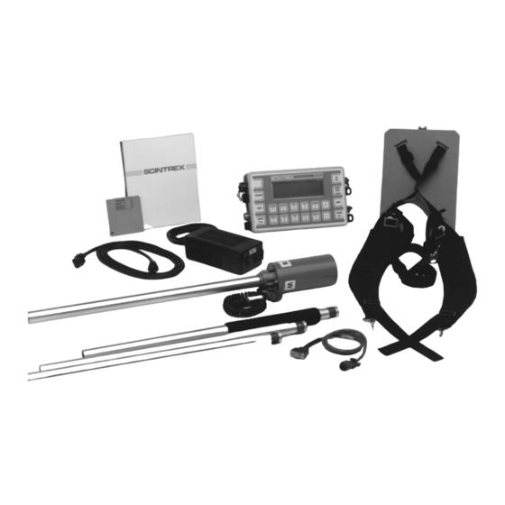
▲ the various options you may have for powering the unit. The following two photographs show all the components (less packing materials) of the standard ENVI-MAG and the ENVI-MAG Gradiometer. Figure A-1 The complete ENVI-MAG total-field kit. A2-1 ENVI-MAG Manual... -
Page 22: Unpacking
Figure A-2 The complete ENVI-MAG gradiometer kit Unpacking The standard ENVI-MAG is shipped in a durable cardboard box that should be retained for storage and shipping. There is an optional carrying/shipping case available as SCINTREX P/N 140 161. The ENVI-MAG with its accessories is packaged in die-cut layers (slabs) of foam. -
Page 23: Repacking
Assembly In order to make the system as compact as possible for shipment and storage, and considering the various sensor configurations available, the ENVI-MAG system requires you to connect up the external components. This section will describe the steps required to completely assemble your instrument. -
Page 24: Total-Field Sensor
(the end with the terminals), the large square plug is at the 9 o’clock position. Use either SCINTREX cable number 780 547 (the shorter one) for the back- pack configuration or cable number 780 550 for the staff configuration. Remove the cable hold-down plate by unscrewing the screws at the 2 o’clock and 4 o’clock positions. -
Page 25: Base-Station Sensor
Orient the sensor so that as you look at the bottom of the sensor (the end with the terminals), the large square plug is at the 9 o’clock position. Use SCINTREX cable number 780 546. Remove the cable hold-down plate by unscrewing the screws at the 2 o’clock and 4 o’clock positions. -
Page 26: Gradiometer Sensors
(the end with the terminals), the large square plug is at the 9 o’clock position. Use SCINTREX cable number 788 028—it has four conductors. Select the lower sensor—it has pairs of terminals at the 12 o’clock and 6 o’clock positions, as well as an attached cable to the terminals at the 6 o’clock position. -
Page 27: Upper Sensor
1 o’clock position. Connect the bare wire of the two-conductor cable coming from the lower sensor to the terminal at the 11 o’clock position. Re-attach the cable hold-down plate. Figure A-5 Gradiometer sensor cabling A2-7 ENVI-MAG Manual... -
Page 28: Installing The Terminal Protective Cover
Assembling the sensor staff You can disregard this section if you are going to be using the ENVI-MAG in the back-pack mode. The sensor staff is shipped in four sections. These sections are located in layer 4 of the packing materials. -
Page 29: Back-Pack Installation
Therefore, you must ensure that the N mark on the sensor faces either magnetic north (or south—either is allowed due to symmetry). Please see “Orientation” on page A5-2 for more details. Figure A-6 Sensor installed in “Back-pack” mode A2-9 ENVI-MAG Manual... -
Page 30: Battery Installation/Exchange
Preparation Battery installation/exchange The ENVI-MAG is shipped without the battery installed. This is the proper procedure, while shipping and storing the instrument, to prevent deep discharge of the battery. Deep discharge can possibly cause permanent damage to the battery and will always shorten the battery life. This situation will occur because a small current is being drawn even if the instrument is turned off. -
Page 31: Using The External Battery Pack
Cold weather use and extended WALKMAG surveys may require more power than the standard battery together with a spare can provide. To satisfy this additional requirement, the External Heavy Duty Battery Pack (SCINTREX part number 788 026) is available. It provides about three times as much power as the standard battery. -
Page 32: Using An External Power Supply
1. The standard internal battery may be left in place. 2. Plug in the end of the cable with the single plug into the Charger Connector at the right-rear side of the ENVI-MAG console. (See item 6 in Figure A-9 on page A3-2.) 3. -
Page 33: The Instrument
Pre-defined operating modes To make the ENVI-MAG easier to use, it has a menu of seven pre-defined configurations, in three modes, to choose from. The menu is obtained by pressing the “SETUP + ON” keys simultaneously. - Page 34 Instrument Figure A-9 The ENVI-MAG console. A3-2 ENVI-MAG Manual...
-
Page 35: Console Description
Cartridge filled with a drying agent. It absorbs any moisture that may get inside the instrument. Battery A rechargeable lead-acid battery in the standard ENVI-MAG configuration. Fuse The standard 1.5A fuse to use with the standard battery. A3-3 ENVI-MAG Manual... -
Page 36: Keypad Description
The response of these multi-function keys depends upon the operation in progress. Note: The function mode of the keys has precedence over the alpha-numeric mode of the keys Figure A-10 The ENVI-MAG keypad. A3-4 ENVI-MAG Manual... -
Page 37: Key Functions
Main operating display. Aborts a data dump. * Accesses the Info. Display, which allows: - setting of data and time, - entering of serial and job numbers, and operator identification, - observation of memory availability. A3-5 ENVI-MAG Manual... - Page 38 * Allows alpha-numeric entry for setups and notes. 1-9, ., A-Z This blank “key” in the upper left corner of the console is not BEEPER actually a key, but a flexible membrane to enhance the PORT loudness of the beeper. A3-6 ENVI-MAG Manual...
- Page 39 Pressing the “ON” and “SETUP” keys simultaneously allows you to select between Basic, Search or Advanced modes. These items/key functions are only operational when you select the advanced operating modes (options 5 to 7) from the initial configuration menu. A3-7 ENVI-MAG Manual...
-
Page 40: Display Screens
Instrument Display screens The ENVI-MAG currently has seven preset configurations. Depending upon which of the configurations you choose to survey with, you may not see all of the various types of displays: ▲ configuration selection menus ▲ help screens ▲... -
Page 41: Cursor
Switching between pages is also done by pressing the “NEXT” key. The display screens are designed so that these multi-page displays do not have separate sub-blocks. All of this is discussed in detail under “Advanced mode data displays” on page A3-30. A3-9 ENVI-MAG Manual... -
Page 42: Pop-Up Windows
MODE:t-fldDUR: 0.5s TUNE FIELD: 60000 AUTO TUNE: TM/DT: OUTPUT:-> OUTPUTING DATA... BASE: TIE: ERASE MEMORY: Chg?:ENT. help:INFO BATT:134 Pop-up Windows locations TIME: 13:40:35 DATE: 94/10/02 SEP: Main Menu: SEP: Chg?:ENT. help:INFO BATT:134 Figure A-13 Sample pop-up windows A3-10 ENVI-MAG Manual... -
Page 43: Help Screens
To toggle to the another help screen, press the “+” or ”-” key. The screens change in a cyclical manner as shown in the above figure. To return to the main operating menu, press the “ESC” key. A3-11 ENVI-MAG Manual... -
Page 44: Operating Displays
Parameter block Location block Title Line locations MODE: t-fld DUR: 0.5s TUNE FIELD: 60000 AUTO TUNE: Display TM/DT: OUTPUT: SEP: Specific BASE: TIE: Info. ERASE MEMORY: SEP: Prompts Chg?:+- help:INFO BATT:134 Battery strength Figure A-15 General display layout A3-12 ENVI-MAG Manual... - Page 45 The following table describes all the parameters in the two blocks of the main menu: Parameter Description Allows you to select the ENVI-MAG operating mode: MODE - total-field magnetometer - gradiometer You must press the “+” or “-” keys to toggle between the modes.
- Page 46 An information pop-up will be displayed telling you to press the “START” key when you are ready. You must have a computer connected using the supplied RS-232 cable (SCINTREX part no. 745 081) and you should be running the ENVIMAP software ( Prepare the Data:Dump...
- Page 47 Parameter Description This option applies a BASE-STATION correction using BASE data supplied from a base-station ENVI-MAG. You must press the “ENTER” key. You need to have the base-station connected as described in “Using base-station data” on page A5-15. A request for confirmation will be displayed in a pop-up window before your data is corrected.
- Page 48 The instrument may turn off without warning when the value drops below 100 and will not allow more measurements. The data however still remains intact in memory, as long as the main battery remains connected. A3-16 ENVI-MAG Manual...
-
Page 49: Basic Mode Data Collection Displays
Graphical display of a survey line. You can press the “NEXT” key to pop-up the graphical display of the precession decay signal of the last reading. Very sharp, rapid decays indicate possible poor signal conditions. The display appears as follows: A3-17 ENVI-MAG Manual... -
Page 50: Search Mode Configuration Display
(available after pressing the “SETUP+ON” keys simultaneously): 4. Search Magnetometer The Main operating display in the Search mode is as follows: MODE: srch. DUR:0.5s TUNE FIELD: 60000 AUTO TUNE: TM/DT: Chg?:+- help:INFO BATT:134 Figure A-19 Search mode main display screen A3-18 ENVI-MAG Manual... - Page 51 The mode should therefore be established by experimenting. However, in general, it is more applicable to site characterization drum use fixed tuning for the location configurations. A3-19 ENVI-MAG Manual...
- Page 52 100 and approximately 140 when the charger is connected. The instrument may turn off without warning when the value drops below 100 and will not allow more measurements. The data however still remains intact in memory, as long as the main battery remains connected. A3-20 ENVI-MAG Manual...
-
Page 53: Search Mode Data Collection Displays
The values that you see for the line and station in the numeric display are the last ones entered in a previous mode. The search mode does not use these for any purpose, so please ignore them. A3-21 ENVI-MAG Manual... -
Page 54: Advanced Mode Configuration Displays
) and the directional part [ The range is from 0 to 99999 with a decimal point as required. The direction allows you to enter the geographical direction or the Cartesian co-ordinates as one of: N,E,S,W, + or -. A3-22 ENVI-MAG Manual... -
Page 55: Instrument Setup Display
Cartesian co-ordinates as one of: N,E,S,W, + or -. Instrument setup display This display enables you to configure the basic data acquisition portion of the ENVI-MAG. This display is accessible with the “SETUP” key. instrument setup instrument setup MAG SETUP: ->menu AUTO ST.INC.:... - Page 56 A request for confirmation will be displayed before the actual erasure takes place. NOTE: The setup parameters remain intact. Enables or disables the LCD display heater. HEATER If the temperature is above -15 degree C, enabling this parameter has no effect. A3-24 ENVI-MAG Manual...
-
Page 57: Magnetometer Setup Display
MODE: tfld default - Total Field Magnetometer ( - Gradiometer - Base Station - Off (will disable the ENVI-MAG). DURATION The measurement duration. A choice of 0.5, 1, or 2 seconds is available. The correct selection depends on the desired measurement accuracy and the spacing of the stations when using the WALKMAG mode of operation. - Page 58 A “yes/no” toggle that applies a BASE- BASE STATION correction using data supplied CORRECT from a base-station ENVI-MAG. You must press the “+” key to toggle You need to have the base-station connected as described in “Using base- station data” on page A5-15.
- Page 59 The instrument goes to "sleep" between readings, for 4 seconds and up. The sensitivity for the analog output for CHART the strip chart recorder. SCALE The following choices are available: 1, 10, 100, 1000, 10000 nT. A3-27 ENVI-MAG Manual...
- Page 60 It is important that this value not be changed during the entire survey. A logical value is the first reading of the base-station on the first survey day. A3-28 ENVI-MAG Manual...
- Page 61 This function is used in the semi-auto- matic mode to save you from having to press another key. Auto Record is always in effect in the base-station operation if the Cycle Repeat function is selected in the ENVI- MAG Instrument Setup. A3-29 ENVI-MAG Manual...
-
Page 62: Advanced Mode Data Displays
Last reading mmmmm.m q.qq ggggg.g ST:sssssd mmmmm.m q.qq ggggg.g sssssd Previous readings mmmmm.m q.qq ggggg.g sssssd mmmmm.m q.qq ggggg.g sssssd MEMF: nn% Free memory Battery strength BATT: bbb Figure A-25 Page 1 of the numeric data display. A3-30 ENVI-MAG Manual... - Page 63 The station number to which the respective magnetic data applies. The value consists of the numeric and directional parts. The percentage of free memory. MEMF Measurements can be made when the memory is full, however the data is no longer recorded. A3-31 ENVI-MAG Manual...
-
Page 64: Graphic Data Display
The display title indicating the data shown by the graph. GRADIENT ggg.g The numeric value indicated by is the respec- tive gradient, at the indicated Line and Station number. The line number along which this measurement took place, consisting of the numeric and directional parts. A3-32 ENVI-MAG Manual... -
Page 65: Recall Displays
The station number is the starting location for the recall, consisting of the numeric and directional parts. The starting time of the recall. This parameter is only present when the Base Station is selected. A3-33 ENVI-MAG Manual... -
Page 66: Recall Data Display
Station. Note that there are two pages of data for the gradiometer. These displays are accessible with the “START” key when in the Recall Setup display . -*MAG*- TOTAL mmmmm.m llll.ld ssss.sd Figure A-29 The recall data display. A3-34 ENVI-MAG Manual... -
Page 67: Modifying The Display Window
A smaller window can be opened up using the “ENTER” key to allow changes. The changes take effect after you next press “ENTER.” -*MAG*- TOTAL mmmmm.m llll.ld ssss.sd SCL: Figure A-30 The Recall display ready for customizing A3-35 ENVI-MAG Manual... - Page 68 Numerical data at the left hand side of the display represents the data at the cursor position. Pressing the “0” key, adjusts the display such that the point at the cursor position becomes the center value of the graph. A3-36 ENVI-MAG Manual...
-
Page 69: Auxiliary Display
This function is reserved for production and service tests. It has no functions for you to use. The lock option allows you to lock the ENVI-MAG setup parameters so that they are not acciden- tally changed. To make any changes, you will have to toggle this option first. -
Page 70: Data Output Display
Instrument Data output display This display allows the selection of: ▲ communication parameters between the ENVI-MAG and the output device such as a computer or printer, ▲ the data format of the output, ▲ and possibly the Line number, if a line by line data dump is desired. - Page 71 The proper setting has to be established experimentally. For example, on some EPSON printers, 7 or 8 bits results in either normal or italic print. The output data format. The formats are described briefly in the following table on page A3-40. A3-39 ENVI-MAG Manual...
-
Page 72: Data Output Formats
XYZ++ is identical to XYZ+ , but the data is XYZ++ now placed into columns. PRN is a format used with software for the SCINTREX MP-3/4 Magnetometer. NOTES outputs a report of all user entered NOTES NOTES, cross-referenced with the Line and Station number. -
Page 73: Notes Display
MACROS are pre-recorded messages of up to 15 MACROS characters. These are used to speed up note entry. It is most advantageous to enter frequently encoun- road fence tered items, such as , and so on. A3-41 ENVI-MAG Manual... -
Page 74: Information Display
Chg?:ENT. help:INFO BATT: bbb Figure A-34 The INFO display. Parameter Description The version number of the ENVI-MAG internal software. Vx.x TIME The current time of day. DATE The present date. This is usually the serial number of the instrument. No use is made of this number by the instrument, there- SER.#... - Page 75 Operating displays Warning: The TIME and DATE must match between the base-station and the portable magnetometer(s) for the base-station style of correction to work properly. A3-43 ENVI-MAG Manual...
- Page 76 Instrument A3-44 ENVI-MAG Manual...
-
Page 77: Setting-Up The Envi-Mag
(advanced) First time operation A special procedure has to be followed to get the ENVI-MAG software set up properly. This procedure is called a cold boot. This assures that all setup parameters are initialized properly and that the memory is cleared. -
Page 78: Cold Boot
This is to ensure that the ENVI-MAG is truly in the OFF state. Press and hold the “AUX/LCD” key. Then press the “ON” key. Release both keys after the beep. -
Page 79: Configuration Menu
First time operation Configuration menu The ENVI-MAG has seven pre-defined configurations in three modes to choose from. See “Pre-defined operating modes” on page A3-1 To change your configuration at any time: Press the “SETUP” and “ON” keys simultaneously. WELCOME ENVI... -
Page 80: General Setup Principles
Setup General setup principles Setting up the ENVI-MAG consists of: ▲ bringing up the various display screens, ▲ moving the cursor to different parameter fields, ▲ then either selecting from a list, or entering appropriate values. It is assumed that you have performed a configuration selection (as shown on... -
Page 81: How To
“+” or “-” keys. Please see also “Select!” on page A4-6. ▲ fill in the parameter fields via the keypad when the prompt is Chg?ENT , by first pressing the “ENTER” key. You will then need to follow the procedures as described for “Enter!” on page A4-6. A4-5 ENVI-MAG Manual... -
Page 82: Select! And Enter
(For more information on editing an entry, please refer to the section “Note entry” on page A4- 25.) Pressing the “ENTER” key again stores the value in memory and the prompt ( ) disappears. > A4-6 ENVI-MAG Manual... -
Page 83: Line And Station Setup
Line and Station setup Line and Station setup For the basic and advanced modes, you will need to enter into the ENVI-MAG the information about your survey grid. This includes: ▲ your starting points on each line, ▲ how far apart each line is, ▲... -
Page 84: Entering The Starting Station
To set your required starting point and separations, just substitute your specific values in the previous steps. Also, keep in mind that entering negative values for the separation parameters causes the respective line or station values to decrement. A4-8 ENVI-MAG Manual... -
Page 85: Basic Mode
ERASE MEMORY: SEP: Chg?:+- help:INFO BATT:134 MODE Move the cursor to Select! tfld tfld grad base from the list of Move the cursor to Select! sec from the following list: sec, sec, TUNE FIELD Move the cursor to A4-9 ENVI-MAG Manual... - Page 86 If the time is out, the corrections will be incorrectly applied. If the date is wrong, no corrections can be performed at all. Enter your survey grid values as described in“Line and Station setup” on page A4-7 You are now ready to start surveying. A4-10 ENVI-MAG Manual...
-
Page 87: Search Mode
(or whatever value is appropriate for your survey area; please refer to Figure B-4 on page B1-14, if this value is unknown) AUTO TUNE Move the cursor to Select! You are now ready to start looking for magnetic objects. A4-11 ENVI-MAG Manual... -
Page 88: Advanced Mode
This mode gives you total control over all the parameters of the ENVI-MAG. You can also use this mode to run the types of surveys defined in the Basic mode, with the additional benefit of more features being available. - Page 89 Advanced Mode AUTO ST.INC: Move the cursor to (automatic station increment) Select! (Since the ENVI-MAG is reading continuously, you want the station value to change only when you reach a station— not with every reading!) LINK REC/START: Move the cursor to...
-
Page 90: Sample Total-Field Setup (Walkmag Or Walkgrad)
Setup Sample total-field setup (WALKMAG or WALKGRAD) The following steps prepare the ENVI-MAG for: ▲ a total-field survey in the WALKMAG or WALKGRAD modes, ▲ with 0.5 second reading period, ▲ automatic tuning, ▲ manual station increment. From the Main operating display proceed as follows: Press the “SETUP”... - Page 91 Please refer to Figure B-4 on page B1-4, if this value is unknown. BASE CORRECT: Ignore TIE CORRECT: Ignore REMOTE: Move the cursor to Select! CYCLE TIME: Move the cursor to Enter! (this parameter is used in the base-station mode only and should be 0 for all other modes). A4-15 ENVI-MAG Manual...
- Page 92 Enter! the ambient magnetic field value, if known, of your survey area.You can also take a reading and enter the first value with good signal. TIE-MODE: Ignore AUTO RECORD: Move the cursor to Select! Press “ESCAPE” to return to the Main operating display. A4-16 ENVI-MAG Manual...
-
Page 93: Sample Stop-And-Go Gradiometer Setup
Advanced Mode Sample stop-and-go gradiometer setup The following steps prepare the ENVI-MAG for a: ▲ gradient survey ▲ in the Stop-and-Go mode, ▲ with a 2 second reading period, ▲ and fixed tuning in the fully manual mode. From the Main operating display proceed as follows: Press the “SETUP”... - Page 94 Enter! the ambient magnetic field value of the survey area. Please refer to Figure B-4 on page B1-4, if this value is unknown. BASE CORRECT: Ignore TIE CORRECT: Ignore REMOTE: Move the cursor to Select! CYCLE TIME: Move the cursor to A4-18 ENVI-MAG Manual...
- Page 95 Select! BASE FIELD: Move the cursor to Enter! the ambient magnetic field value of the survey area, if known. TIE-MODE: Ignore AUTO RECORD: Move the cursor to Select! Press “ESCAPE” to return to the Main operating display. A4-19 ENVI-MAG Manual...
-
Page 96: Sample Base-Station Setup
Setup Sample base-station setup The following steps prepare the ENVI-MAG as a: ▲ magnetic base-station, ▲ with a 2 second reading period, ▲ and fixed tuning. From the Main operating display proceed as follows: Press the “SETUP” key and the INSTRUMENT SETUP display appears. - Page 97 Enter! the ambient magnetic field value of the survey area. Please refer to Figure B-4 on page B1-4, if this value is unknown. BASE CORRECT: Ignore TIE CORRECT: Ignore REMOTE: Move the cursor to Select! CYCLE TIME: Move the cursor to Enter! CHART SCALE: Move the cursor to A4-21 ENVI-MAG Manual...
- Page 98 Move the cursor to Select! BASE FIELD: Move the cursor to Enter! for now your ambient magnetic field value, if known. TIE-MODE: Ignore AUTO RECORD: Move the cursor to Select! Press “ESCAPE” to return to the Main operating display. A4-22 ENVI-MAG Manual...
-
Page 99: Information Display
▲ job number, ▲ serial number, ▲ operator identification. From the main operating display proceed as follows: Press the “INFO” key and the Information display appears: scintrex data acquisition system v1.0 TIME: hh:mm:ss SER.#: sssssssss DATE: yy:mm:dd JOB #: jjjjjjj... - Page 100 Enter! the instrument serial number or other permanent identification. JOB #: Move the cursor to Enter! a job number or other unique identifier for the survey. OPERATOR: Move the cursor to See “Note entry” on page A4-25 for detailed instructions on how to enter alphanumerics. A4-24 ENVI-MAG Manual...
-
Page 101: Note Entry
From the Main operating display proceed as follows: Press “NOTE” and the Note display appears. NOTES: #nnnnnnnnnnnnnnnnnnnnnnnnnnnnnnnn MACROS: 1:ccccccccccccccc 2: ccccccccccccccc 3:ccccccccccccccc 4: ccccccccccccccc 5:ccccccccccccccc Chg?:ENT. BATT:bbb Press the “ENTER” key. Press the “2” key repeatedly until appears. A4-25 ENVI-MAG Manual... - Page 102 Unique notes, belonging to one reading only, are entered in the same way, with the exception that step 10 is omitted. The note will then be recorded along with the data. The note entry field is then cleared. A4-26 ENVI-MAG Manual...
-
Page 103: Display Intensity Control
LCD Intensity Data Output Factory Test # Lock Reprogram System Select function Press the “+” or “-” key to adjust the intensity of the display to your satisfaction. Press “ESCAPE” twice to return to the Main operating display. A4-27 ENVI-MAG Manual... -
Page 104: Parameter Lock
Setup Parameter lock instrument setup mag setup The ENVI-MAG parameters can be locked to prevent accidental change. To do so, proceed as follows. From the main operating display: Press the “AUX/LCD” key to bring up the Auxiliary display. auxiliary functions... -
Page 105: Reprogramming The Operating System
Advanced Mode Reprogramming the operating system The flash EPROM’s (erasable, programmable read only memory) of the ENVI-MAG can be updated from your computer using the software supplied by SCINTREX. At the computer Note the name of the upgrade program (usually DASPROM.SYS) written on the label of the supplied disk. - Page 106 7. When the download is finished, i.e. 100% complete on the PC, wait for about 10 to 15 seconds for the ENVI-MAG to reprogram. The ENVI-MAG will then automatically perform a cold boot and you are ready to survey.
- Page 107 If the download is interrupted (power shut-down at either the PC or ENVI end), you will have to repeat the above steps. If the ENVI-MAG does not reboot for some reason, you must power the unit off and then on. The screen may not be functional, but the bootstrap program is running.
- Page 108 Setup A4-32 ENVI-MAG Manual...
-
Page 109: Operating The Envi-Mag
Operating the ENVI-MAG The information in this chapter is not intended to be a complete tutorial on magnetic surveying, rather it highlights the unique features of the ENVI-MAG. Section 2–Applications of this manual covers this subject in more detail. This chapter will cover the following: ▲... -
Page 110: Orientation
It is good practice to get familiar with this feature as it is a useful tool in diagnosing difficulties. -*MAG*- hh:mm:ss TOTAL GRADIENT LN:llllld mmmmm.m ggggg.g ST:sssssd mmmmm.m ggggg.g sssssd mmmmm.m ggggg.g sssssd mmmmm.m ggggg.g sssssd MEMF: nn% BATT: bbb A5-2 ENVI-MAG Manual... -
Page 111: Other Sources Of Noise
(Figure A-4 on page A2-5) to operate in the base-station mode, depending upon your particular circumstances. Note: The long sensor cable is particularly susceptible to interference. You should ensure that the sensor cable is kept away from other cables and electrical equipment, especially electrical generators. A5-3 ENVI-MAG Manual... -
Page 112: Repeated Surveys Lines
If it is necessary to repeat a set of measurements on a survey line, you should take certain precautions to ensure data handling is done in the most effective manner. The ENVI-MAG recalls or outputs repeated data sequentially by time at the same locations, resulting in unsightly (or unintelligible) recall displays. You will also have to substantially edit your data files to properly use them with the ENVIMAP software. -
Page 113: Walkmag
This should give you a better understanding of what you will be required to do when doing your ENVI-MAG survey. ▲ It is assumed that the lines are marked and pegged intervals of 10 units. -
Page 114: Check Your Setup
Move the cursor to Enter! 10. Move the cursor to Press the + key. The Line number increments to 18. Proceed to Line 18 N, Station 50 W. Press the “START” key. Proceed immediately walking to the East. A5-6 ENVI-MAG Manual... -
Page 115: Walkgrad Gradiometer Survey
A walking type of gradiometer survey is done in the same manner, with the following exceptions: MODE: GRAD ▲ At the select ▲ The standard back plate is not suitable to carry this large sensor configuration. The specially designed WALKGRAD backpack is best suited for this purpose. A5-7 ENVI-MAG Manual... - Page 116 This results in highest precision, as this eliminates the possibility of a small magnetic signature caused by the ENVI-MAG console. The sensor has to be oriented for each reading. Figure A-39 A typical gradiometer configuration.
-
Page 117: Manual Mode-Total-Field/Gradiometer (Semi-Automatic)
“1” key to enter the note “fence 1”. You may also enter your Macro or any unique note after the measurement, but before you Press the “RECORD” key. After completing 50 W, proceed to 50 W on Line 18 N. A5-9 ENVI-MAG Manual... -
Page 118: Automating Your Measurements
In the Instrument setup, move the cursor to Select! YES mag setup AUTO RECORD: In the , move the cursor to Select! YES To operate as a total-field magnetometer in the Stop-and-Go mode, make the mag setup: MODE: T-FLD following change in the screen, A5-10 ENVI-MAG Manual... -
Page 119: Base-Station Operation
1 - 3 to set up the instrument (or at least to verify proper settings as shown in the “Sample base-station setup” on page A4-20). You may have to cold boot your ENVI-MAG and select one of the advanced configurations (5 to 7). Check your setup Set up Line and Station Number to the actual location of the base-station. -
Page 120: Start Operation
You can also press the “0” (zero) key to center the graph vertically. *Optional steps Note: Data scrolled off the screen may be inspected with the RECALL feature. This however requires interruption of data acquisition. A change in the graph sensitivity does not affect the recorder sensitivity. A5-12 ENVI-MAG Manual... -
Page 121: Search Mode
Line and Station number, as well as, separation are not needed or used. Do the “Instrument setup” on page A4-12 as shown, except set: CYCLE REPEAT ▲ : to CYCLE DELAY: ▲ Do the “Sample base-station setup” on page A4-20 as shown, except set DURATION: 0.5 sec ▲ A5-13 ENVI-MAG Manual... - Page 122 ) total-field sensor and cable. Press the “NUM/GRAPH” key to display the graph. Press the “+” or “–” key to change the sensitivity of the graph. You can also press the “0” (zero) key to center the graph vertically. A5-14 ENVI-MAG Manual...
-
Page 123: Survey Data Correction Procedures
You can only use base-station data when you have selected one of the advanced (5–7) survey configurations. This procedure describes the correction when using ENVI-MAG only. The correction with different instruments must be done indepen- dently on a computer. Caution: The base-station correction physically modifies the data of the mobile units, but does not alter the base-station’s data. -
Page 124: Tie-Point (Tie-Pt) Mode
Select! YES. You will now see a warning message on the right side of the display of the field unit indicating that the raw data in the field ENVI-MAG will not be preserved. Press the “START” key on both. Either one can be started first. -
Page 125: Line Type-Collecting Data
4. Call up the mag setup: display 5. Move the cursor to TIE-MODE: 6. Select! LINE. 7. Return to the Main operating display STN: 8. Move the cursor to in the Locations block on the right side. A5-17 ENVI-MAG Manual... - Page 126 Tie-points as the first data that you store in memory, i.e. before you survey any lines. This ensures that they will not be erased when clearing memory to make room for the next day’s data. A5-18 ENVI-MAG Manual...
-
Page 127: Tie-Point Correction Procedure
5. Press the “START” key. 6. You will now be asked to confirm the correction operation by pressing either the “Y” or” “N” keys. 7. When finished, Press the “ESCAPE” key. A5-19 ENVI-MAG Manual... -
Page 128: Remote Operation
It also controls the output of the data output stream, on the data output connector, while measuring in other modes. To enable the remote control of your ENVI-MAG: Connect the ENVI-MAG to the serial port of the controlling computer using the RS-232 cable P/N 745 081. mag setup:... -
Page 129: Data Output
ENVI-MAG. Please contact SCINTREX if you are interested in a specialized high- speed downloading program. The RS-232 cable, SCINTREX P/N 745 081, is the link between the ENVI-MAG data output connector and the serial port of the computer or printer. -
Page 130: Xyz
-8.57143 0 56488.17 0.27 7.298889 0 -1.94 -7.85714 0 56488.55 0.26 7.299028 0 -2.77 -7.14286 0 56486.25 0.28 7.299167 0 -2.78 -6.42857 0 56484.66 0.27 7.299306 0 -4.17 -5.71428 0 56481.91 0.24 7.299444 0 -5.49 -5 0 56478.62 0.26 7.299722 0 -6.3 A6-2 ENVI-MAG Manual... - Page 131 -7.85714 0 56488.55 0.26 7.299028 0 -2.77 -7.14286 0 56486.25 0.28 7.299167 0 -2.78 Note /N pipe: -6.42857 0 56484.66 0.27 7.299306 0 -4.17 Data -5.71428 0 56481.91 0.24 7.299444 0 -5.49 -5 0 56478.62 0.26 7.299722 0 -6.36 A6-3 ENVI-MAG Manual...
-
Page 132: Xyz
0.28 7.298750 0 -1.54 -8.57143 56488.17 0.27 7.298889 -1.94 -7.85714 0 56488.55 0.26 7.299028 -2.77 -7.14286 56486.25 0.28 7.299167 -2.78 /N pipe: -6.42857 56484.66 0.27 7.299306 -4.17 -5.71428 56481.91 0.24 7.299444 -5.49 56478.62 0.26 7.299722 0 -6.36 A6-4 ENVI-MAG Manual... -
Page 133: Prn
Output formats The PRN format is compatible with software written for the Scintrex MP-3/4 magnetometer. /-------------------------- S C I N T R E X ----- -----//! Line____: 0.00000 N /! Date____: 93/05/21 /! Job_____: 1 /! Operator: r /! Serial__: 3 /! Basefld_: 56490.0... -
Page 134: Notes
In the output, it shows them with their respective line and station values. For example, from the data in the PRN file on the previous page you would see the following: / Y: Line 0.00000 N / X: Stn 7.14286 W/ pipe A6-6 ENVI-MAG Manual... -
Page 135: Basic Mode
9600 baud, 8 bits, 1 stop bit and no parity, while the data format is set as XYZ++ (see page A6-4 for details). Connect the ENVI-MAG to the serial port of your computer, using the RS-232 cable (SCINTREX P/N 745 081). -
Page 136: Advanced Mode
Please refer to “Data output display” on page A3-38 for detailed explanations of all the parameters. Connect the ENVI-MAG to the serial port of your computer, using the RS-232 cable (SCINTREX P/N 745 081). To receive data, start your ENVIMAP or other communications program. - Page 137 BAUD: Move the cursor to Select! your desired baud rate. Note: The baud rate on the ENVI-MAG must match the baud rate on the output device for successful communication. BIT: Leave : at 0 and FMT: Move the cursor to Select! the desired output data format (see “Output formats”...
-
Page 138: Dumping Data
Press the “NEXT” key until the cursor rests within the left sub-page. all data recorded Move the cursor to: Press the “START” key. Options: Press the “STOP” key to temporarily suspend dumping. Press the “ESCAPE” key to abort the dump. A6-10 ENVI-MAG Manual... -
Page 139: Specific Data
Move the cursor to one of the three data types at the field: T-FLD GRAD. BASE Press the “START” key. Options: Press the “STOP” key to temporarily suspend dumping. Press the “ESCAPE” key to abort the dump. A6-11 ENVI-MAG Manual... -
Page 140: Line By Line
Press the “START” key. Options: Press the “STOP” key to temporarily suspend dumping. Press the “ESCAPE” key to abort the dump. Repeat steps 4 to 8 as required. Press the “ESCAPE” key to return to the Main operating display. A6-12 ENVI-MAG Manual... -
Page 141: Erasing Data From Memory
Erasing data from memory After you have successfully dumped your data to a computer and have verified that it is all there, you should free up the ENVI-MAG’s memory to prepare for your ERASE MEMORY next survey. This is accomplished by activating the option. -
Page 142: Advanced Mode
You will be asked to confirm that you actually want to erase all the data from memory by pressing the “Y” key. You will then see the Block memory free increment on the prompt line as it is cleared. A6-14 ENVI-MAG Manual... -
Page 143: Maintenance And Repair
It should then be recharged as soon as possible. However, the instrument draws a small current even when turned off. If the ENVI-MAG is left in a discharged state, for even a few days, then the battery will eventually deep discharge. -
Page 144: One Battery
Connect the charger to the charger input connector. Flip the switch on the charger to On. Observe the charging light at the left hand side of the ENVI-MAG console. It will be On while charging at a high rate and turn Off when the battery is nearly charged. -
Page 145: Two Batteries
Connect the charger to the charger input connector. Flip the switch on the charger to On. Observe the charging light at the left hand side of the ENVI-MAG console. It will be On while charging at a high rate and turn Off when the battery is nearly charged. -
Page 146: Periodic Maintenance
Therefore, it is good practice to wash the sensor(s) periodically with soap and water. Desiccant exchange Small amounts of moisture may possibly enter the ENVI-MAG console, even though it is fully sealed. A cartridge filled with a drying agent (desiccant) is located under the battery cover, refer to Figure A - 44 on page A7-3 for the exact location. -
Page 147: Fuse Replacement
Two fuses holders are provided under the battery cover of the ENVI-MAG, as shown in Figure A - 44 on page A7-3. One is for a 1.5 A quick, standard North American fuse (Scintrex P/N 512 018). The other fuse holder is for a 5 x 20mm European fuse. -
Page 148: Instrument Disassembly/Assembly
Repeat steps 1 to 12 in reverse order to assemble the console again. If available, apply a small amount of oil or grease to the O-rings. Tighten up the screws with a medium-sized slotted screwdriver. Do not overtighten. A7-6 ENVI-MAG Manual... -
Page 149: Cable Repair
Cable Wire Color Connector Pin Shield/Bare Total Field (780 547 & 780 550) White Shield/Bare Green Gradiometer (788 028) White Black Shield/Bare Base Station White (780 546) Black Outside External Power (788 029) Black Center A7-7 ENVI-MAG Manual... -
Page 150: Trouble Shooting
Display is invisible Incorrect LCD intensity 1. If no data is in the setting instrument, perform a cold boot. 2. Adjust LCD intensity using AUX/LCD button to access option. 3. Turn on the heater if below minus 15° C. A7-8 ENVI-MAG Manual... - Page 151 Numeric Page 2 display bar chart. 2. Readings may be impossible to make in this situation. External interference Readings may be (e.g. power line) impossible. No fluid in the sensor (shake and listen Contact SCINTREX. for sloshing sound) A7-9 ENVI-MAG Manual...
- Page 152 Correction must be time made externally on a computer. Cannot recall data No respective line Set recall parameters or station (or time, to match survey if base-station). parameters, i.e. LN, SEP , STN, SEP may be out a digit. A7-10 ENVI-MAG Manual...
-
Page 153: Reference Information
ENVI-MAG Chapter Reference information ENVI-MAG technical specifications Total field range: 20,000 to100,000 nT Total field absolute +/-1 nT accuracy: 0.1 nT at 2 second reading time, reduced at Sensitivity: other reading times. Sensor spacing: 0.5 metre (Gradiometer) Fully solid state. - Page 154 Handshaking is done by X-On/X-Off. Data dump of all acquired data in memory or on a mode by mode and line by line basis in XYZ or Data output format: printer listing format. Separate dump for “Notes”. A8-2 ENVI-MAG Manual...
- Page 155 ENVI-MAG technical specifications 0 to 999 mV full scale output voltage with keyboard selectable range of 1, 10, 100, 1000 Analog Output: or 10000 nT full scale. On the LC Display in graphic format. Based on Data Recall: time for the base station, on line and station basis for other modes.
-
Page 156: Instrument Parts List
Null Modem 210 154 Charger 400 139 Battery 2.3 Ah 400 078 Battery 7.2 Ah 400 080 Fuse 1.5A 512 018 Fuse 5 A 512 049 Carrying/Shipping Case (Optional) 140 161 External Trigger Interface Kit 788 033 A8-4 ENVI-MAG Manual... -
Page 157: Warranty & Repair
SCINTREX for repair. If the problem cannot be resolved remotely, our personnel will request that you then send the instrument to our plant for the necessary repairs. -
Page 158: Shipping Instructions
No instrument will be accepted for repair unless it is shipped prepaid. After repair, it will be returned collect, unless other arrangements have been made with SCINTREX. Please mention the instrument’s serial number in all communications regarding equipment leased or purchased from SCINTREX. - Page 159 ▲ one set attached to the air waybill. SCINTREX instruments are manufactured in Canada, consequently there is no customer duty payable in Canada. It is advisable to state on the customs documents the following: “...
- Page 160 Reference A8-8 ENVI-MAG Manual...
- Page 161 Applications Table of Contents Applications for the ENVI-MAG Magnetic surveying overview ........B1-1 Introduction ..............B1-1 Basic magnetic theory ............ B1-1 What is being measured? ..........B1-1 Anomalies............... B1-3 Shape ..............B1-5 Amplitude ..............B1-6 Variations in the Earth’s magnetic field ......B1-7 Diurnal variation ............
- Page 162 Post-survey procedures ..........B3-11 Clean-up site if required..........B3-11 Data correction ............B3-11 Data transfer ............... B3-12 Processing data ............B3-12 Field example ..............B3-12 Columbia test site—Waterloo, Ontario ......B3-12 Grid layout.............. B3-13 Bibliography ..............B3-17 B-ii ENVI-MAG Manual...
-
Page 163: Magnetic Surveying Overview
Introduction These application notes review some of the numerous environmental applications for which the ENVI-MAG is designed. The first chapter will give a general overview of the purpose and scope of a magnetometer survey. In the second chapter, we shall discuss the planning of a magnetometer survey carried out with the ENVI-MAG, Environmental Magnetometer/Gradiometer, within a specific environmental application. - Page 164 (represented by the vector in the figure). This local vector adds to the Earth’s field vector to produce the total-field vector . What the ENVI-MAG in the total- field mode measures, is the projected amplitude of the total-field T in the direction of the dominant Earth’s field .
-
Page 165: Anomalies
This is always the case with buried drums, as we shall see in Chapter 3. Anomaly Noise Envelope Distance Figure B-3 Typical anomalous signature. ENVI-MAG Manual... - Page 166 Applications Figure B-4 The intensity of the Earth's magnetic field. ENVI-MAG Manual...
-
Page 167: Shape
The fall-off rates for a dipole or line of dipoles would vary as a cube power (1⁄ r ), while that of a monopole or line of monopoles would fall-off as a square power (1⁄ r Figure B-5 Typical targets. ENVI-MAG Manual... -
Page 168: Amplitude
The deeper the object, the weaker and broader the peak on the profile will be. This is illustrated in the following figure (Figure B-7). ENVI-MAG Manual... -
Page 169: Variations In The Earth's Magnetic Field
However, they are not predictive and are usually not a problem when conducting magnetic surveys. This diurnal drift can cause a variation of the order of 50 nT/Hour. The following figure (Figure B-8) illustrates a typical diurnal variation of the total field. ENVI-MAG Manual... -
Page 170: Micro-Pulsations
(Figure B-9). These can present a problem when you are surveying in that they may appear similar to anomalies caused by buried objects. Figure B-9 Typical micro-pulsations (after Breiner, 1973). ENVI-MAG Manual... -
Page 171: Magnetic Storms
In Canada, geomagnetic forecasts are available through the Geophysics Division of the Geological Survey of Canada, while in the United States this information is available from NOAA. This information will greatly help you in planning your magnetometer survey. ENVI-MAG Manual... -
Page 172: Removing Magnetic Variations
This method is not as accurate as using a base-station, but if the field is not changing rapidly, it is quite adequate to locate an anomaly. This technique may be the most cost-effective, as it only requires one magnetometer. ENVI-MAG Manual... -
Page 173: Magnetic Targets
3 metres (10 feet) will give rise to an anomaly of 10 nT. Also, Benson et al., 1982 have calculated that the total field response in nT for different target distance and mass. This is show in the form of a chart presented in (Figure B-11). ENVI-MAG Manual... -
Page 174: Induced And Remanent Magnetism
The intensity of the induced magnetization is directly related to the ambient field by the susceptibility, and is therefore the induced part of the disturbance. Susceptibilities are measured in cgs units. ENVI-MAG Manual... - Page 175 Another example is shown in (Figure B-13). This simplifies the previous example by keeping the orientation of the traverse line and the depth of the body constant, i.e. the measuring geometry. The only parameter that is varying is the direction of the permanent magnetization. ENVI-MAG Manual...
- Page 176 When this is added to the Earth’s magnetic field and then measured only as the scalar amplitude, the results may not be exactly as expected. ENVI-MAG Manual...
-
Page 177: Survey Planning
For instance, if an anomalous peak is only 2 metres in width or length and data points are taken only every five metres in a square grid pattern, there is a very good chance that the peak will be missed altogether! ENVI-MAG Manual... -
Page 178: Line And Station Spacing Vs. Anomaly Width
This detectability threshold of twice the sample spacing is sometimes referred to as the Nyquist frequency in more advanced magnetic data processing. The following figure (Figure B14) illustrates these points. Figure B14 Sampling interval and anomaly resolution. B2-2 ENVI-MAG Manual... -
Page 179: Precision And Accuracy Of Surveys
The gradiometer approach is intermediate in cost, as only one unit is required, but you are compromising your ability to detect deep and subtle anomalies, since you are only measuring the rate of change of the field. B2-3 ENVI-MAG Manual... -
Page 180: Tuning
WALKMAG The most commonly used mode of operation in environmental applications is the WALKMAG mode. With the ENVI-MAG, the operator can take almost continuous readings (at sampling rates of up to every 0.5 seconds) in this mode. For a walking pace of 3 km (2 miles) per hour, data will be collected at approximately every half a metre (or about every two feet). -
Page 181: Stop-And-Go
This is illustrated in the following figure (Figure B16), which shows the set-up of a stop-and-go survey. Figure B16 Set-up for a Stop-and-Go survey. B2-5 ENVI-MAG Manual... -
Page 182: Gradiometer
When you are examining the data after it has been plotted, the ability to correlate known noise sources with the anomalies on your map greatly aids in the proper identification of the buried targets. B2-6 ENVI-MAG Manual... -
Page 183: Grid Layout And Orientation
Long structures or bodies which are aligned in a parallel fashion are not usually encountered in environmental applications (except pipelines), the direction of the targets are most often random. Consequently, most environmental grids are laid out in square pattern. B2-7 ENVI-MAG Manual... - Page 184 Applications B2-8 ENVI-MAG Manual...
-
Page 185: Survey Procedures And A Sample Survey
Typical environmental grids consist of survey lines spaced every metre or two, with data points every metre. The following figure (Figure B-18), illustrates a typical survey grid, with base lines at 0 and 40 and survey lines every two metres. B3-1 ENVI-MAG Manual... - Page 186 Then mark each survey line with wooden stakes driven into the ground. The heads of the stakes should preferably be marked with fluorescent paint. The base line implementation is illustrated in the following figure (Figure B-19). B3-2 ENVI-MAG Manual...
- Page 187 10 metres. You may also choose not to mark every survey line, but only survey lines every 5 metres. The position of the intermediary survey lines would be approximated by the operator. This is illustrated in the following figure (Figure B-20). Figure B-20 Typical flagged survey line. B3-3 ENVI-MAG Manual...
-
Page 188: Multiple Grids
As is often the case, you may want to survey several grids in the course of a single day without having to dump the data after each grid. The ENVI-MAG does not store any information about which grid a particular set of lines belong to. -
Page 189: Tie-Point Line And Loop Mode Corrections
However, it should ne noted that neither of these methods are as accurate or precise as the base-station correction. A technical paper on this subject (Magnetic Correction Techniques) is available from SCINTREX. The tie-point line method uses data collected along the base line (or rarely, tie-lines) as reference points to correct for the diurnal drift of magnetic data. - Page 190 Compare this to the tie-point line method shown in the previous figure (Figure B-21) Figure B-22 Typical tie-point method in loop mode survey. B3-6 ENVI-MAG Manual...
-
Page 191: Search Mode
The taking of notes is done quite easily with the ENVI-MAG using the “NOTE” key. You can pre-enter a choice of five cultural noise sources (macros) that you are most likely to encounter during the survey. -
Page 192: Sensor Mounting And Orientation
It is also very important to maintain a constant orientation of the sensor while you are measuring and walking from station to station. In other words, do not sway to and fro while walking during a WALKMAG survey. B3-8 ENVI-MAG Manual... -
Page 193: Rough Terrain
Station lag and Herring-boning The measurement that you make with the ENVI-MAG does not take place im- mediately due to the cycle time of the instrument, which is at best 0.5 sec- onds. Consider also, that during a WALKMAG survey you, the operator, are continuously moving. -
Page 194: Surveying In The Stop-And-Go Mode
WALKMAG mode, ▲ the sensor staff should be held at arm’s length when taking a measurement, ▲ it is very important that the sensor be maintained in a constant and proper orientation for each line. B3-10 ENVI-MAG Manual... -
Page 195: Post-Survey Procedures
This will allow you to visually locate anomalies, as well as, determine the intensity of the anomalies. This is done using the ENVI-MAG’s graphic display capabilities of the magnetometer data. You can also visually monitor the magnetic activity at your base station with this feature. -
Page 196: Field Example
Further processing of the data can be carried out using the optional GEOSOFT map processing software. This optional software allows you to create colour plots, image maps and 3-D presentations, as well as providing enhanced gridding, modelling and interpretation tools. Contact your SCINTREX representative for more details. Field example Columbia test site —... -
Page 197: Grid Layout
(1) metre should be used for this type of site. This was the case. For the same reason, the WALK-MAG mode with readings taken every 0.5 seconds and stations updated every 10 metres was used for this type of site. B3-13 ENVI-MAG Manual... - Page 198 The results are presented in the following captions in contoured data form for the total field survey and in profile form for the gradiometer survey. (Figure B-28) illustrates the contoured total field data and (Figure B-29) the contoured vertical gradiometer data. B3-14 ENVI-MAG Manual...
- Page 199 Field example Figure B-28 Columbia test site total-field contoured data. B3-15 ENVI-MAG Manual...
- Page 200 Applications Figure B-29 Columbia test site vertical gradient contoured data. B3-16 ENVI-MAG Manual...
-
Page 201: Bibliography
Westphalen, O. and Rice, J., 1992, Drum Detection: EM vs. Mag. Some revealing tests; Proceedings of the 6th National Outdoor Action Conference, p.665-688. Telford, W.M., Geldart, L.P ., Sheriff, R.E., Keys, D.A., 1976, Applied Geophysics, Cambridge University Press, New York, 860 pp. B3-17 ENVI-MAG Manual... - Page 202 Applications B3-18 ENVI-MAG Manual...
-
Page 203: The Envimap Software
RAM disks and GEOTEMP........... C2-9 STEP 4: Selecting your video card type ......... C2-10 STEP 5: Select your printer and port ........C2-11 Printer ................. C2-11 Port ................C2-11 Activate your selections ..........C2-11 STEP 6: Completing Installation........... C2-12 C - i ENVI-MAG Manual... - Page 204 Create a map..............C3-14 Draw the map............C3-14 Map surround options..........C3-16 Reference grid options ..........C3-19 Contour options ............C3-21 Plot ................C3-24 Screen Preview ............C3-24 Hardcopy ..............C3-25 Convert to DXF ............C3-26 C -ii ENVI-MAG Manual...
-
Page 205: Processing System Steps
The sequence of steps in using the processing system are: 1. Prepare the data The data must first be collected using the ENVI-MAG (see Section B - Applications). The ENVIMAP system will copy the data from the ENVI-MAG and create a file on your computer. This file can be directly processed to produce a map. -
Page 206: Conventions Used In This Section
(See “Type styles” on page vii.) Convention A filename, environment variable, directory, Monospaced menu selection, or any computer command. The keys you are required to press. If these Keycaps are not separated by commas, you must press all the keys displayed simultaneously. C1-2 ENVI-MAG Manual... -
Page 207: Installation And Getting Started
1. Your copy of the ENVIMAP System has been delivered with disks that match your floppy drive size—either 3½" or 5¼" disks. 2. You have 2.4Mb of free disk space on your hard drive to install the system. C2-1 ENVI-MAG Manual... -
Page 208: Installation Procedure
C:\ENVIMAP . into directory – or – Will install the system from drive B:\INSTALL B: D: \ENVIMAP D:\ENVIMAP . into directory You will be prompted to insert each disk into the source drive as they are needed. C2-2 ENVI-MAG Manual... -
Page 209: Step 2: Product Registration
STEP 3: System configuration After all the files have been expanded and installed, the installation procedure will automatically run your copy of ENVIMAP . You will be presented with the following installation menu: C2-3 ENVI-MAG Manual... -
Page 210: Menu Usage Overview
This section will cover the various aspects of the ENVIMAP interface and how to use it. If you are already comfortable with using menu systems, then you can jump to the next section “Configuring” on page C2-8 to finish your setup of the ENVIMAP system. C2-4 ENVI-MAG Manual... -
Page 211: The Menu Screen
The actions are triggered by either pressing the key, in combination with the highlighted letter on the button, or by clicking on the button using the mouse. 5. Status bar — this line displays your current working directory and any ENVIMAP messages. C2-5 ENVI-MAG Manual... -
Page 212: Using The Keyboard And Mouse
After you have selected the task you want to do and have entered the correct information, you must press (Go! ) to complete the task. -button flashes at the bottom right portion of your screen when- ever you are in a dialogue screen. C2-6 ENVI-MAG Manual... -
Page 213: Using The Mouse
(per- taining to the highlighted field) appears. This message will stay on the screen until you either click anywhere inside of the Help box or click RIGHT mouse button. C2-7 ENVI-MAG Manual... -
Page 214: Configuring
You can also use a RAM drive to speed up operations (See “RAM disks and GEOTEMP” on page C2-9). Note: This temporary area should have a minimum of 2Mb free space and you must specify a drive. Do not leave this blank. C2-8 ENVI-MAG Manual... -
Page 215: Ram Disks And Geotemp
To set up a RAM disk, refer to your DOS manual (see the RAMDISK command for DOS 5 and 6, or the VDISK command for earlier versions of DOS), or your third party RAM disk software manual. The more C2-9 ENVI-MAG Manual... -
Page 216: Step 4: Selecting Your Video Card Type
Click on Go or Press Alt-G to complete selection. cleaR clear All Command Help List eXit G:\ENVIMAP Figure C-4 Video and Printer setup menu. Select the class of graphics card type that matches your set-up and go on to the next step. C2-10 ENVI-MAG Manual... -
Page 217: Step 5: Select Your Printer And Port
Please activate the pick list and select the port. Usually you can select PRN: , the default, if you are uncertain. 3. Activate your selections You must now activate both the video and printer selections by either pressing or by clicking on the button. C2-11 ENVI-MAG Manual... -
Page 218: Step 6: Completing Installation
ENVIMAP Installation STEP 6: Completing Installation If you encounter any difficulty, please contact Scintrex ENVI-product support for assistance (our telephone and fax numbers are on the cover page, or See “HELP-Line” on page C-ix) Re-boot the system by simultaneously pressing the keys to complete this stage of the installation. -
Page 219: If You Have Problems
8. You are asked to re-boot the computer. The installation procedure is now complete. You should now be able to start working with the ENVIMAP System. If you have encountered any problems, please refer to the following installation notes. C2-13 ENVI-MAG Manual... -
Page 220: Manual Installation
7. Select the SYSTEM CONFIGURATION menu. 8. Configure your system by selecting appropriate configuration options. 9. Edit your AUTOEXEC.BAT CONFIG.SYS files and make sure they include the necessary components described in section 2. 10. Re-boot your computer, checking for errors. C2-14 ENVI-MAG Manual... -
Page 221: Error Messages
ENVIMAP installation. You will have to attempt a manual installation. (See “Manual installation” on page C2-14.) “ Out of environment space” during re-boot If during re-boot the following DOS message occurs: Out of environment space C2-15 ENVI-MAG Manual... -
Page 222: Could Not Load Sushiø.exe" When Trying To Run Envimap
Cannot find files during system configuration \ENVIMAP This problem is most likely caused by not being in the directory when running the INSTALL menu. The current directory is displayed in the bottom left corner of the ENVIMAP screen. C2-16 ENVI-MAG Manual... - Page 223 If you have problems \ENVIMAP If it is not set to the directory: Press ▲ ▲ Enter \directory, where directory is the name of the ENVIMAP directory C2-17 ENVI-MAG Manual...
-
Page 224: Cannot Find Files When Running The Software
1. Set the default directory to the ENVIMAP directory. 2. Enter: ENVIMAP 3. From the SYSTEM CONFIGURATION menu, select the Video and Printer Setup option. 4. Select either the EGA or VGA option to match the capabilities of your computer. C2-18 ENVI-MAG Manual... -
Page 225: Cannot Plot To A Printer
1. Setting the default directory to the \ENVIMAP directory. 2. Run ENVIMAP 3. Select the System Configuration option. 4. Select the Video and Printer Setup option. 5. Select Printer and choose the appropriate printer from the list. C2-19 ENVI-MAG Manual... -
Page 226: Envimap Reference
The ENVIMAP processing system is a simple to use, menu driven package that allows you to process and create plots from data gathered by the SCINTREX ENVI-MAG. This system is specifically designed to work only with this and other SCINTREX instruments in the environmental series. -
Page 227: Limitations
As with any package, there are some limitations to what ENVIMAP can deal with and accomplish. To add more functionality, you can buy the complete Geosoft Mapping System directly from SCINTREX. Data (XYZ) files The data input can consist of an unlimited number of XYZ points, limited only by the disk space on your computer. -
Page 228: The Menu Screen
The actions are triggered by either pressing the key in combination with the highlighted letter on the button or by clicking on the button using the mouse. 5. Status bar — This line displays your current working directory and any ENVIMAP messages. C3-3 ENVI-MAG Manual... -
Page 229: Using The Keyboard And Mouse
After you have selected the task you want to do and have entered the correct information, you must press (Go! ) to complete the task. The GO -button flashes at the bottom right portion of your screen whenever you are in a dialogue screen. C3-4 ENVI-MAG Manual... -
Page 230: Using The Mouse
By clicking on the HELP button of the button bar, a help message pertaining to the highlighted field will pop up. This message will stay on the screen until you either click anywhere inside of the Help box or click the RIGHT mouse button. C3-5 ENVI-MAG Manual... -
Page 231: Pick Lists
How to cancel If you do not wish to make a selection simply press the key to close the list. C3-6 ENVI-MAG Manual... -
Page 232: File Lists
³ ³ ³ Drive ³ ³ Drive ³ ³ ³ ↓ ³ ³ ³ Cancel ÔÍÍÍÍÍÍÍÍÍÍÍÍÍÍÍÍÍÍÍÍÍÍÍÍÍÍÍÍÍÍÍÍÍÍÍÍÍÍÍÍÍÍÍÍÍÍÍÍÍÍÍÍÍÍÍÍÍ; output merged XYZ file name (.XYZ assumed): cleaR clear All Command Help List eXit G:\ENVIMAP Figure C-8 ENVIMAP file pick list C3-7 ENVI-MAG Manual... -
Page 233: The Dos Command Window
You can select the Command function anytime you see a Command button on the Button bar by either pressing or by clicking on it. The following figure shows a typical DOS command window: C3-8 ENVI-MAG Manual... -
Page 234: Shelling To Dos
DOS button This is accomplished by pressing when it is available on the Button bar. Returning to ENVIMAP To get back to the ENVIMAP system you must: 1. enter EXIT at the DOS prompt 2. press C3-9 ENVI-MAG Manual... -
Page 235: Menu Reference
If you only have a single drive, this will usually be “ C:\ ”. This will then tell ENVIMAP to use the drive’s root directory that you specified for creating temporary files. You cannot leave this blank. C3-10 ENVI-MAG Manual... -
Page 236: Video And Printer Setup
The classes of supported devices include Epson-compatible 9 and 24-pin dot matrix, Hewlett- Packard PCL compatible laser, and some HP compatible ink-jets. Please contact SCINTREX ENVI- technical support, if you cannot get your printer to work with one of these configurations. Printer Port You must inform ENVIMAP to which port output should be directed. -
Page 237: Prepare The Data
This section allows you to adjust the communications speed between the ENVI-MAG and your PC. The default setting of 9600 should suffice. You must also ensure that the settings on the ENVI-MAG match those on your PC for the two devices to properly communicate. -
Page 238: Merge Data Files
XYZ file name (.XYZ assumed): cleaR clear All Command Help List eXit G:\ENVIMAP Figure C-13 Merge data files screen All the selections on this screen have file lists attached so that you can easily merge data from various directories and drives. C3-13 ENVI-MAG Manual... -
Page 239: Create A Map
"Plot" selection in the main menu. ↓ Data file name: envimag.xyz Field to plot: total field Preview when done? YES ground units: meters Sheet orientation: Landscape Title: ENVI-MAG Sample Data Sub-Title: Sample Contour Map Sub-Title: Test Survey cleaR clear All Command Help List... - Page 240 This will be the main title of your map. It will be plotted in the centre towards the bottom edge of your map sheet. Sub-Title 1 This line will be plotted in a smaller size immediately below the Title line. Sub-Title 2 This line is plotted immediately below the previous sub-title line. C3-15 ENVI-MAG Manual...
-
Page 241: Map Surround Options
“data plus margins” will adjust the size of the frame to the size of the data, which will always be the same or smaller than the printer page. C3-16 ENVI-MAG Manual... - Page 242 A negative offset will be down the map sheet. North Arrow This group of options allows you to control the placement, orientation and annotation of the north arrow. 1. Show North Arrow? A YES or NO option to show the north arrow. C3-17 ENVI-MAG Manual...
- Page 243 This option allows you to specify how much, in centimetres on the plotted map, to offset the north arrow in the horizontal direction from the reference point mentioned above. A negative offset will be down the map. C3-18 ENVI-MAG Manual...
-
Page 244: Reference Grid Options
By default, the system will automatically determine a suitable spacing between grid lines. If the selected spacing is not suitable, you can specify your own in ground units. Note: If you select a spacing that is too narrow, the grid annotations may overlap. C3-19 ENVI-MAG Manual... - Page 245 ✚ plus ✖ cross or "x" ● ■ ▲ triangle ◆ small diamond 3. Marker Size You must specify the marker height in millimetres. A suitable size will be automatically chosen if you leave this field blank. C3-20 ENVI-MAG Manual...
-
Page 246: Contour Options
If this is not specified, an appropriate contour interval will be automatically chosen. We recommend that the first time a data set is contoured, the defaults should be used. Adjustments can then be made as necessary. For example, to contour at 10 nT intervals, enter 10. C3-21 ENVI-MAG Manual... - Page 247 This is a value in ground units. Any areas that are farther than this distance from the data points will not be gridded/contoured. Caution: If this value is set for too small a value, you may get unwanted holes in your contoured results. C3-22 ENVI-MAG Manual...
- Page 248 4. Maximum iterations This specifies the maximum number of times the grid mesh will be adjusted to get the grid within the tolerance range specified for the input data. C3-23 ENVI-MAG Manual...
-
Page 249: Plot
Plot file name: envimag.plt cleaR clear All Command Help List eXit G:\ENVIMAP Figure C-20 Plot file preview dialogue screen Plot file name Enter the name of the PLT file you wish to preview. A file list is available. C3-24 ENVI-MAG Manual... - Page 250 PC. The file can then be plotted to the appropriate device by using the DOS COPY/B command to copy the file to the printer port. This is great for making multiple copies ! PRN plot-files can be very large. C3-25 ENVI-MAG Manual...
-
Page 251: Convert To Dxf
Command Help List eXit G:\ENVIMAP Figure C-22 The AutoCAD DXF output dialogue screen Plot file name Enter the plotfile name to be converted. The output file will have the same name, but with a .DXF file extension. C3-26 ENVI-MAG Manual... - Page 252 ENVI-MAG Index...
- Page 254 Sample gradiometer setup A4-17 Auxiliary functions display A3-5 Sample INFO display setup A4-23 Sample Instrument setup A4-12 Sample Note entry A4-25 Search mode setup A5-13 Back Plate A2-2 setup display A3-25 Back-pack A2-2 installation A2-9 Tie-point correction procedure A5-19 ENVI-MAG Manual Index-...
- Page 255 External Pack A2-11 external power A3-3 installation A2-10 sensor A3-3 removal A2-3 Console A2-2 standard A2-2 description A3-3 Battery charging A7-1 Contact numbers single battery A7-2 geomagnetic forecasts B1-10 two batteries A7-3 Baud rate A3-37 C3-13 Beeper port A3-6 Index- ENVI-MAG Manual...
- Page 256 A3-3 instrument setup A3-23 Display Intensity control A4-27 advanced mode A3-36 mag setup A3-25 A4-14 A4-18 Formats A3-38 main A4-5 format A3-37 A3-38 Main operating setup A6-8 advanced mode A3-22 Data processing B3-12 Note entry A3-6 ENVI-MAG Manual Index-...
- Page 257 Diurnal variations B1-7 B2-3 Installation C2-2 removing B1-10 Interface C2-4 manual installation C2-14 command plotting C3-24 executing C3-9 Product registration C2-3 window C3-8 System configuration C2-3 environment C2-15 trouble-shooting C2-13 shell C3-9 drum location A3-12 A3-14 A3-19 Index- ENVI-MAG Manual...
- Page 258 Fuse Replacement A7-5 INFO A3-40 INFO key A3-5 Information display A3-5 A3-40 A4-23 Input Geomagnetic forecasts alphanumeric A4-6 contact numbers B1-10 numeric A4-6 GEOTEMP C2-9 INSTALL program C2-13 GO button C2-8 C3-4 Installation Gradient A3-30 A3-31 software C2-2 ENVI-MAG Manual Index-...
- Page 259 Magnetic Keyboard C2-6 anomaly B1-3 pick lists C3-4 shape B1-5 selecting items C2-6 C3-4 declination B1-1 Keypad A3-3 dipole B1-5 description A3-4 inclination B1-1 monopole B1-5 storms B1-9 targets B1-11 LCD A3-3 vector B1-1 heater A3-24 viii Index- ENVI-MAG Manual...
- Page 260 ENVI-MAG vi Numeric Data Display A3-29 erasing A6-13 Numeric input A4-6 Nyquist frequency B2-2 percent free A3-30 A3-40 Menu ENVI-MAG Configuration A4-3 screen components C2-5 ON/OFF key A3-5 sections C3-3 – Operating displays A3-12 A3-40 Micro-pulsations B1-8 Minus key (-) A3-6...
- Page 261 Page numbering scheme ix display A3-6 A3-32 Panning (graphic display) A3-33 Setup display A3-32 Parameter fields RECALL key A3-6 accessing A4-5 RECORD key A3-6 Parameters Reference Grid C3-19 Advanced mode A3-22 REMOTE basic mode A3-13 advanced A3-27 Index- ENVI-MAG Manual...
- Page 262 Site Characterization A3-12 site characterization A3-14 A3-19 parameters A3-19 SMARTDRV C2-9 C3-10 sample setup A4-11 Software sample survey A5-13 ENVI-MAG version no. A3-40 Sections vii installation C2-2 Selecting items Spare parts kit A2-4 keyboard C3-4 mouse C3-5 ENVI-MAG Manual Index-...
- Page 263 B3-4 advanced A3-22 precision B2-3 basic A3-15 Survey lines Staff A2-2 repeated A5-4 assembling A2-8 Surveying SCINTREX MP-3/4 A2-8 WALKMAG mode B3-7 Standard Battery A2-2 Symbols viii Starting line System configuration C2-8 C3-10 entering A4-8 Starting station entering A4-8...
- Page 264 A3-13 A3-19 A3-27 A4-14 fixed A3-14 A3-19 A3-27 A4-17 Type styles vii Typeface conventions vii C1-2 Unlocking parameters A4-28 Unpacking A2-2 Upgrade kits vi VDISK C2-9 VGA C2-10 Video card EGA, VGA C2-10 Video graphics C3-11 xiii ENVI-MAG Manual Index-...
- Page 265 Index Index- ENVI-MAG Manual...
Need help?
Do you have a question about the ENVI-MAG and is the answer not in the manual?
Questions and answers