
Subscribe to Our Youtube Channel
Related Manuals for Ambrell EasyHeat 0112

Summary of Contents for Ambrell EasyHeat 0112
- Page 1 Technical Handbook Induction Heating Systems for 1.2kW – 2.4kW Models 0112, 0224 File Name 801-9309.doc Part Number 801-9309 Revision Rev F ECN# 1606-08 Mike Bond Approved Dan King Date 06/28/2016...
- Page 2 Rev E (ECN1308-06) was written to: • Update back panel figures • Correct Serial Port enabling via converter kit information Rev F (ECN1606-08) was written to: • Correct the “Electrical Equipment Input” table Ambrell SARL Ambrell Corporation Ambrell, Ltd. Ambrell B.V. France...
-
Page 3: Table Of Contents
801-9309.doc Table of Contents Introduction ........................5 Safety Considerations ....................6 Front Panel ........................7 Rear Panel ........................8 Assembly ........................9 How Your EASYHEAT Works ..................13 Home Zone ........................ 14 Control Zone ......................20 Detailed EASYHEAT Operation ................25 Equipment Maintenance .................... - Page 4 Notes: In this manual, these symbols indicate: a step in a procedure § manual sections lighted indicators on the equipment A notice that requires your EASYHEAT (RHS) Free Front with remote heat station special attention; may pertain to safe operation of the equipment A notice that requires your special attention due to...
-
Page 5: Introduction
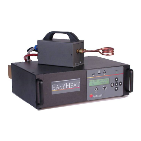
801-9309.doc Your EASYHEAT is a solid-state induction heating system that converts single-phase line voltage to a 1.2kW or 2.4kW terminal output over a range of radio frequencies (RF) and voltages. This energy is delivered to a series-resonant circuit - including your coil - where a precisely controlled magnetic field is created around your work-piece. -
Page 6: Safety Considerations
Your EASYHEAT uses RF energy to raise the temperature of your work-piece. Most of this RF energy is transmitted into the work-piece and some is transmitted into the air. Physical Risks During the HeatOn cycle, high RF voltages are present at your work-coil. There are several risks, which we instruct you to protect against: High Temperatures: take steps to prevent personal contact with the work-piece you •... -
Page 7: Front Panel
801-9309.doc Handles Display Status AC indicator START/STOP Navigation Hoses and RF Cable (RHS) Hoses & RF Cables The remote heat station attaches here. A circular plastic connector conveys RF energy to the cable and heat station; plastic tubing routes cooling water to and from the heat station. -
Page 8: Rear Panel
Water connections (A) Your EASYHEAT uses circulating water to cool internal components and the coil; inlet and outlet connections for the entire system are made at the rear. Internal flow-switches are used to interrupt heating operations if this flow is inadequate. Temperature sensors are used to reduce heating if the internal temperature rises too high Terminal block (CTB1) (B) Electrical connections are made here for all input and output signals (§3). -
Page 9: Assembly
801-9309.doc Take these factors into consideration as you determine where to install your system: • availability of water and drain for Free-Front models: same procedure - at rear • availability of AC power outlet Attach heat station (if not attached) unscrew protective cap insert indexed heat station plug tighten ring nut... - Page 10 Rack/panel Mounting Your EASYHEAT is mountable in your panel or 19” rack (3U); observe these steps and requirements: 18.3 (465) 5.2 (132) 2.25 (57) 17.5 (445) 1.5 (38) panel cutout Not to scale; inch (mm) unscrew/remove 4 rubber feet on unit base (panel) provide cutout and mounting pattern per above;...
- Page 11 801-9309.doc Certain cooling configurations can significantly restrict flow, limiting EASYHEAT’s efficiency. Under these conditions, you must supply water to the unit from 3/8” tube and adapt to ¼” at the unit if: • supply line lengths exceed 5 feet • EASYHEAT is in series with another power supply or component Insert drain tube end fully into fixture labeled OUTLET (To remove tubing, press retaining ring while pulling on tube.) Flow monitoring...
- Page 12 Introduction...
-
Page 13: How Your Easyheat Works
801-9309.doc When you turn HeatOn, (details, next page) this equipment concentrates an electromagnetic field within the coil diameter. When you put your metal part into the coil, this field causes internal electric currents to circulate in your part. Friction from these currents heats your part. -
Page 14: Home Zone
operates in the Home zone (illustration). Within this When you turn it on, E zone, you can adjust output levels, set the timer and turn RF power on and off: Status LEDs indicate what your E is doing: READY: waiting to heat; no faults detected HEAT ON: power is being output FAULT: heating interrupted, fault detected Timer... - Page 15 801-9309.doc Do this... Observe... open water-valve for the system check drain; assure water is flowing check the work-coil assure there is no work-piece yet check condition of (any) safety all safety devices are clear, electrically barriers or limit switches closed turn on E AC Power and Ready LEDs (are ON)
- Page 16 Sometimes, you may see that the output frequency approaches either end of the operation range of E and the display advises you to increase or decrease capacitance. Please call your Ambrell office for assistance should this happen and we will supply you with the appropriate capacitors. How Your E...
- Page 17 801-9309.doc Status LEDs This guide will help you understand the operation of your E LED Status and system notices are relevant if your part is in the coil during HeatOn. Status and notices displayed after you remove your part can be ignored Ready is waiting to heat;...
- Page 18 Touch-panel features START/STOP When starting the unit from the front panel, use these buttons to (de)activate heating. Press START to begin induction heating. HeatOn (LED) shines and the display is updated with operating data. START operates only within HOME zone Press STOP to halt induction heating (2-button start type, below).
- Page 19 801-9309.doc Navigation This map will help you understand operation and programming your E Each touch-pad button is represented in the map, showing the effect touching each one has depending on your location in the map Amps/ Watts displayed Setpoint Timer START STOP Temps, Faults...
-
Page 20: Control Zone
. Control This is how you review or change operating characteristics of the E Zone is accessible only while heat is off. From the Home zone, press , the Control Zone menu is shown. Use ► to select from 4 sub-menus, detailed below (defaults underlined). ►... - Page 21 801-9309.doc Com Protocol Com Protocol Com Protocol Com Protocol Terminal Mode : Use ► to select. Terminal Com Protocol mode is the only mode currently supported ►Terminal Mode Communication Communication Communication Communication None Communication RS485 4 Wire: (Required for eView) ►None RS485 2 Wire: LAN:...
- Page 22 1button: HeatOn only while button is pressed (or CTB1 signal closed), ceases when button is released.(or CTB1 signal opens) Control From Control From Control From Control From Front Panel: during HeatOn, RF output Control From follows setpoint entered at front panel ►Front Panel Rear Panel: your analog signal controls output...
- Page 23 801-9309.doc ► ► ► ► Menu Selection ►System Status ► ► (Once this screen is displayed, press ; use ▲/▼ to select operating features): Display the temperature of active components HS65F AM72F on the heat sink (HS) and the internal ambient Increase Tap air (AM) and any active (unresolved) Fault notices (§2.3)
- Page 24 ► ► ► ► Menu Selection ►Heat Station ► ► (Once this screen is displayed, press ; use ▲/▼ to select operating features): Heat Station Heat Station Heat Station Heat Station This enables the power supply to operate after Choose Menu you make changes to the heat station ►Modify Tap configuration, or if you select from two different...
-
Page 25: Detailed Easyheat Operation
801-9309.doc This section details how to: • interpret the Status LEDs • understand system Faults and Advisories • program and execute continuous and multi-step heat-cycles (profiles) Interpret Status LEDs This guide will help you understand the operation of your E LED Status and system notices are relevant if your part is in the coil during HeatOn. - Page 26 ● ● to Control zone, ►Status then for fault notice AC Power; indicates E is ON; see the Status screen for notices How Your E Works...
- Page 27 801-9309.doc Interpreting Faults, Limits and Advisories Your E communicates information about the way it’s operating. This section explains these conditions and what you can do (4) to respond to them. Fault Heating interrupted; fault detected; correction required to Control zone, ►Status then for fault notice ●...
- Page 28 Multi-step profile Case: the part is brought to temperature and held in three steps. From Control zone: Do this... Observe... select ►Adjust Profiles Select Profile then ►A press ; this selects Profile A 0.0A 0.0A Start Untimed►A1 Data Time Each step has 3 data points: with A1 selected, press ►...
-
Page 29: Equipment Maintenance
Ready, turn off water; assure Fault; restore water. If no Fault, flow switch is stuck; do not operate further! Equipment safety is compromised. Call Ambrell service 6 months coolant level; top-off if required appearance; flush & replace if dark or cloudy system;... -
Page 30: Calibration
Your E system has been calibrated by our test facilities; this means that the displayed output level accurately represents the rms current delivered over the RF cable to the heat station. If you have recurring calibration requirements for your E equipment, we offer this calibration service: •... -
Page 31: Smartburst Technology
801-9309.doc The E heat stations contain one or more water cooled capacitors, rated for current under laboratory (rather than real-world) conditions. The E systems make use of Smartburst technology which allows users to approach these higher current limits in actual use under many real world conditions while maintaining the safety margins required for long operating life. - Page 32 How Your E Works...
-
Page 33: Customizing Your Easyheat
801-9309.doc You can control your E in different ways: START / STOP can be controlled from the front panel or remotely • • output level can be set from the front panel, remotely or with optional multi- step profiles you specify •... - Page 34 0-10V Standard, this input is ground-referenced. If your controlling equipment demands an isolated input, call Ambrell about our input isolating option kit Depending on the signal source you plan to use (0-10Vdc is the default configuration), follow these instructions to change.
- Page 35 801-9309.doc START/STOP (CTB1:3-5) Case: use two external signals, switches or isolated contacts to control RF heating: START signal is normally-open, active-closed, STOP is normally-closed, active-open. 2-Button... Electrical Touch-pad ►Setup Attach your signal: Start From ► RPan CTB1:3 = START Start Type ► 2-button N.O.
- Page 36 Flow switches Do not modify or disconnect the internal connections. The flow switches protect your from thermal damage if cooling water to the heat sink or to the coil is inadequate. To add your optional normally-open flow switch, remove jumper at CTB1:6-7, connect your flow switch wires.
- Page 37 801-9309.doc 24V source & E-stop (CTB1:8-16) Case: You use internal 24V power supply to drive your remote status signaling (ex., LEDs); you include your E-stop switch LEDs, resistors and EStop; your equipment ground Electrical Touch-pad Connect to internal solid-state contacts to None complete your indicator signaling (shown);...
-
Page 38: Optional Pendant
This section has information about (optional) hand-held pendant controllers for use with . Explained are: • available styles • pendant wiring diagram Control requirements • E • operating instructions Available Styles At this writing, there are two models available: • 3-lights, Start/Stop (upper) •... - Page 39 801-9309.doc Pendant wiring diagram Your pendant simply attaches to the rear of your E at CTB1; we have made all the wiring connections. If you change this wiring or want to operate without the pendant, remember this: • a jumper is required from 4:com to 5:Stop •...
- Page 40 EASYHEAT Control requirements Your EASYHEAT has been configured to operate with your pendant; the actual model you have is addressed in the table below. These are the steps we took (see :§2.2 for Control instructions) to configure the unit. You will need this information if you change the settings.
- Page 41 The RS485 serial communication port is a standard feature of EASYHEAT. To enable serial communications, a converter kit is required. This kit with installation instructions is available (PN 305-0248). Contact Ambrell to order this kit. You can configure your own serial communication hardware and software to address EASYHEAT.
- Page 42 To Configure the E If the converter kit (PN 305-0248) has been purchased and installed, follow these steps to prepare your E to make use of the serial communication option. takes place when Home zone is displayed; Serial communication with E while in Control mode, the EASYHEAT will not respond to all serial commands.
- Page 43 801-9309.doc To Configure Your Computer The following is one way to configure the serial port of your computer; you may have your own devices or means of making the communications connection. Do this... Observe... launch HyperTerminal from Programs > Accessories > Communication (or other serial communication application) enter a ‘connection name’...
- Page 44 Command set This table gives examples of each command’s use and the range of the data you can use in the command ‘argument’. The address is required and the commas between the address, command and arguments are required; do not insert spaces! Input is not case- sensitive.
- Page 45 801-9309.doc Returns the CHDR and CTIME settings of the power supply. See CHDR and CTIME commands for description. none 1,c? Continuous reply includes a description header line followed by a data line. The data line includes Heat status, set point, amps out, power out, frequency and timer.The header line may be changed to repeat at different intervals based on cdata...
- Page 46 ctl-rs485 none Selects control location to be RS485. 1,ctl-rs485 ctrloff none Turns off RS485 keyboard control of set point. 1,ctrloff Enables RS485 control of set point. Use "]" right bracket key ctrlon none 1,ctrlon to increase set point. Use "[" left bracket key to lower set point. Multi-line single reply, PS address, Heat status, Setpoint, data none...
- Page 47 801-9309.doc Turns the EKOHEAT RS485 transmitter on continuously. Normally the transmitter is disabled after a transmission, this command will cause the transmitter to remain in the transmit state all the time. This will aid with noise problems that can be txon none caused while the RF is on and the RS485 cable is picking up...
-
Page 48: Eview Induction Heating Software
eVIEW is a PC based application that interfaces with EASYHEAT and EKOHEAT power supplies. eVIEW allows the operator to visualize, analyze, and store induction heating data while the power supply runs. Key parameters such as power, frequency, and tank voltage (or current) are displayed on a real time chart and saved in a spreadsheet. -
Page 49: Tap Adjustment (Ihs Only)
• Capture external analog signals such as temperature. eVIEW is an accessory product offered for EASYHEAT and EKOHEAT power supplies. Contact Ambrell to learn more about eVIEW and see for yourself how PC based monitoring can improve your efficiency and productivity! Under certain heating conditions, E may ‘suggest’... - Page 50 has sensed that a more appropriate tap setting is called for. If you elect to follow this advice, follow these steps Do this... Observe... Increase Tap (example) press for Status STOP unit is Ready turn off AC power switch at rear AC power LED, panel are not remove line cord from rear of unit lighted...
-
Page 51: Cap Replacement (Ihs Only)
801-9309.doc Under certain conditions, E may suggest changing your capacitor. Call Ambrell service to order a replacement capacitor, then follow these instructions: Do this... Observe... turn off AC power switch at rear AC power LED, panel are not lighted remove line cord from rear of unit use Philips screwdriver to remove screws securing cover;... -
Page 52: Tap Adjustment; 1-Cap Rhs
Under certain heating conditions, E may ‘suggest’ changing your RF transformer tap settings (§2, Advisories...). For example: ►250A 234.00s during HeatOn, an asterisk is shown on 220A *190kHz the display. To read the message, press for Status HS65F AM72F There may be a message like this: Increase Tap You can ignore this suggestion if: •... -
Page 53: Tap Adjustment; 2-Cap Rhs
801-9309.doc persists, follow instructions ...until heating without Under certain heating conditions, E may ‘suggest’ changing your RF transformer tap settings (§2, Advisories...). For example: during HeatOn, an asterisk is shown on ►250A 234.00s the display. To read the message, 220A *190kHz press for Status... - Page 54 persists, follow instructions ...until heating without Technical Information...
-
Page 55: Cap Replacement; 1-Cap Rhs
801-9309.doc Under certain conditions, E may suggest changing your capacitor. Call Ambrell service to order replacement capacitors, then follow these instructions: Do this... Observe... turn off AC power switch at rear AC power LED, panel are not lighted use small blade to release handle caps use Philips to remove 2 handle screws remove handle;... -
Page 56: Cap Replacement; 2-Cap Rhs
Under certain conditions, E may suggest changing your capacitor. Call Ambrell service to order replacement capacitors, then follow these instructions: Capacitors are always installed, used and replaced in equal pairs! Never install unequal cap values or operate your unit with only one cap installed. -
Page 57: Technical Information
801-9309.doc Power Supply Feature Value Units Dimensions 5.5 x 15.75 x 17 (140 x 400 x 432) in (mm) HxDxW Internal access 10 counter-sink screws to open top Mounting 19” rack or bench-top Weight 28 (12.7) lb (kg) Construction: aluminum Finish front panel black anodized Your system uses and produces high voltages! Only trained or guided service persons... -
Page 58: Environmental
Customer input Port Active CTB1: Description Limits Remote input analog 0 – 10 Vdc (Zin = 21kΩ) see §3 4-20mA (Zin = 250Ω) Start closed provide isolated contact closure* Stop open flow switch closed 19Vdc@ 0.1A opened contact = ΩFault E-stop open 15-16... -
Page 59: Theory Of Coil Design
remove this page and replace with 801-9038...
Need help?
Do you have a question about the EasyHeat 0112 and is the answer not in the manual?
Questions and answers