Advertisement
Quick Links
Assembly instruction
Date:
File:
RBDIY-CTSVCOA-1.1
Title:
CATCH VCO-A DIY
REF:
Thank you for purchasing this ReBach DIY Voltage-controlled Oscillator !
We hope you enjoy the construction and use of this beautiful VCO.
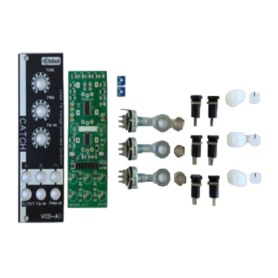
Package Content:
- 1x Main PCBA RB1815
- 1x Front PCB RB1816
- 2x 10K Pot-meter
- 1x 50K Pot-meter
- 2x 10K trimmer
- 3x M7 Washer
- 3x M7 Nut
- 6x 3.5mm Jack incl nut
- 3x Knob White
- 3x Knob cab
- 1x Ribbon power cable
- 2x 3mm screw
Note:
Check if all the above-mentioned parts are present in the packaging before starting construction! Contact
your supplier if a part is missing before you start building.
You the customer agree that if the packaging has been opened and some construction steps have been
made, you are responsible for a successful construction.
Follow the steps in this building instructions carefully to prevent errors
The conditions of your supplier are respected by ReBach!
Note:
11-04-20
Project:
Version:
HW version:
Page:
No rights can be deducted from this document.
© 2020 ReBach –
1.2
1.1
1
www.rebach.eu
Remark:
Advertisement

Summary of Contents for ReBach CATCH VCO-A DIY
- Page 1 CATCH VCO-A DIY HW version: REF: Page: Thank you for purchasing this ReBach DIY Voltage-controlled Oscillator ! We hope you enjoy the construction and use of this beautiful VCO. Package Content: - 1x Main PCBA RB1815 - 1x Front PCB RB1816...
- Page 2 Assembly instruction Date: 11-04-20 Project: Remark: File: RBDIY-CTSVCOA-1.1 Version: Title: CATCH VCO-A DIY HW version: REF: Page: Overview Place 10K trimmers on the PCB All parts Positions TR1 and TR2 on PCB. Front side PCB Solder Place pot-meters on the PCB...
- Page 3 11-04-20 Project: Remark: File: RBDIY-CTSVCOA-1.1 Version: Title: CATCH VCO-A DIY HW version: REF: Page: Solder Place the PULS out jack socket Check potentiometer contacts are in a good position and solder. PULS is in the middle of the top row...
- Page 4 Assembly instruction Date: 11-04-20 Project: Remark: File: RBDIY-CTSVCOA-1.1 Version: Title: CATCH VCO-A DIY HW version: REF: Page: Place Front Place Front Place the front and enter the Jack solder tabs through the PCB Insert the solder pins through the PCB Tip:...
- Page 5 Assembly instruction Date: 11-04-20 Project: Remark: File: RBDIY-CTSVCOA-1.1 Version: Title: CATCH VCO-A DIY HW version: REF: Page: Solder Tighten Jacks Tighten the jacks with your wrench Solder the jack socket contacts Tip: Use a little flux for a perfect solder...
- Page 6 Assembly instruction Date: 11-04-20 Project: Remark: File: RBDIY-CTSVCOA-1.1 Version: Title: CATCH VCO-A DIY HW version: REF: Page: Place knobs Place knobs Allow minimal space between knob and nut ! Place knobs and caps Tip: Align black line on cap to the fully left...
- Page 7 Project: Remark: File: RBDIY-CTSVCOA-1.1 Version: Title: CATCH VCO-A DIY HW version: REF: Page: Tuning To calibrate this VCO, you need either a tuner or a different VCO or keyboard/Synth. Your second VCO or SYNTH is used as the reference source! For good results, please let the VCO warm up for at least 5 minutes! Set the two trimmers (TR1 &...
Need help?
Do you have a question about the CATCH VCO-A DIY and is the answer not in the manual?
Questions and answers