
Summary of Contents for AV-EXIM AUSBAU
- Page 1 Operation manual Mobile hydraulic ramps AUSBAU 1 из 12 All rights reserved. No part of this manual may be used in any form or by any means without written permission of the copyright owner.
-
Page 2: Table Of Contents
Contents Introduction ............................. 3 1. Purpose of equipment ......................... 4 2. Specifications ............................4 3. Package supply........................... 4 4. General idea of the product and its design ..................4 5. Description of the hydraulic station...................... 5 6. Transportation of the product ......................6 7. -
Page 3: Introduction
Introduction Dear customers, We thank you for your purchase of the AUSBAU mobile hydraulic ramps. Please read these operating instructions carefully before use. The ramps must be operated in accordance with the requirements of this manual, as well as other regulations regarding work safety requirements. -
Page 4: Purpose Of Equipment
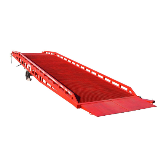
Mobile hydraulic ramps are special, auxiliary equipment that is used together with a forklift or pallet jackfor loading and unloading of goods. With the AUSBAU mobile hydraulic ramp, a forklift can carry out unloading and loading operations of grouped cargoes inside a truck/wagon, driving directly into it from the ground. It helps the company significantly save its labor resources, increase efficiency, speed up cargos turnover, demonstrating an overall economic effect. -
Page 5: Description Of The Hydraulic Station
The middle and upper parts of the ramp have decks that provide maximum grip of the forklift wheels on the surface and free drainage of water. The connection lip is made of thick steel sheet. In the central part of the product there is a hydraulic group that provides raising and lowering of the ramp. The hydraulic group consists of a hydraulic station (includes a manual pump, oil flow valve and oil tank) and two hydraulic cylinders (single-acting with return to initial position under the ramp's own weight). -
Page 6: Transportation Of The Product
1 – Hydraulic cylinder. 2 – High pressure hoses. 3 – Shut-off valve for pumping. 4 – Oil transfer hose. 5 – Oil tank with necktube. At rest state (valve open) the oil is in the expansion tank and all hydraulic components are under no pressure. The weight of the ram presses oil from the hydraulic cylinders into the oil tank through the high pressure hoses and the pump. -
Page 7: Ramp Usage Intensity
8. Ramp usage intensity The product is designed to operate in a mode in which the throughput capacity of one ramp should not exceed 160 tons of cargo transported through it daily. In case of exceeding the limit of intensity of use, the manufacturer declines the responsibility to provide warranty and post-warranty service of the equipment. -
Page 8: Operating Rules
10. Operating rules Before you start operating the ramp: 1. Visually verify that the ramp is in the correct position for operation. 2. Check the oil level. 3. Raise the ramp above the floor of the vehicle (50 mm higher) by closing the valve on the pump and inflate pressure using the pump. -
Page 9: Technical Service
During operation: 1. The connecting lip of the ramp remains on the loading surface of the truck (container) at a depth not less than the connection lip length minus 50mm. 2. The hydraulic system remains free from pressure for the ramp to track the height of the supporting transport (this height varies depending on the load on the truck pendant). -
Page 10: Maintenance
Thick Grease Points: Thick grease points (Lithol-24 or equivalent) are shown below and should be checked at least every 6 months. All grease points should be wiped down periodically with kerosene(or equivalent) to remove dirt and fresh grease should be applied. 1 –... -
Page 11: Typical Faults And Solutions
+36 1 800 16 67 +31 970 102 808 98 E-mail: mail@av-exim.com 11 из 12 All rights reserved. No part of this manual may be used in any form or by any means without written permission of the copyright owner. -
Page 12: Appendix 1. Work Scheme For Unloading/Loading
Appendix 1. Work scheme for unloading/loading Set the height of the ramp to +50 mm from the bottom of the truck (container). The distance between the ramp frame and the truck should be max 50 mm. Turn the hydraulic pump valve counterclockwise so that the connecting lip rests on the bottom of the truck or container.
Need help?
Do you have a question about the AUSBAU and is the answer not in the manual?
Questions and answers