Table of Contents
Advertisement
Quick Links
Advertisement
Table of Contents

Summary of Contents for AREQUIPMENT E400
- Page 1 USER MANUAL: E400 LS (Lateral Sliding) MAN AR 63/07/18/0...
- Page 2 Headquarters Rua de S. Caetano 459/519 Apartado 526 4411-701 Canelas Vila Nova de Gaia Portugal T. +351 227 157 100 F. +351 227 121 144 comercial@arequipment.com www.arequipment.com...
-
Page 3: Table Of Contents
Index Basic Information What’s the E400? ………………………………………………………………………………..……….….……………………...4 1.Specifications E400…………………………………………………………………….……….…..…………………………….5 2.Electric Components………………………………………………………………………………………….……….………...6 3.Electric Installation……………………………………………………………………………………………….…………..…..7 Instructions - Loading/Unloading 4.Unloading Operation: (with trolley installed) ……………………………………………………………………..…8 5.Loading Operation (with trolley installed) …………………………………….……………………………….……10 6.Emergency button………………………………………………………………….………………………………………...…11 7.Unloading Operation: (without trolley installed) ………………….………………………………..……………12 8.Loading Operation (without trolley installed) ………………………………………………………..……………13 9.Lateral Sliding (Optional) ……………………………………………………………………………………..……………..14... -
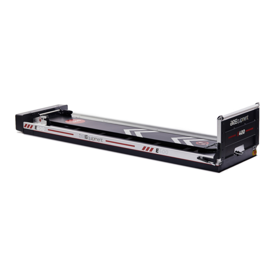
Page 4: What's The E400
E400 The E400 is an electric loader for Mondial Stretcher. The main function is the attachment of the stretcher to the table and it’s usable in different types of vehicles. The electrical power eases the access to the ambulance cell and enables the user to make less effort. -
Page 5: Specifications E400
1. Specifications • Weight: 105 kg • Maximum load capacity: 300Kg • Dimensions: 2220 x 635 x 475 mm • 3 attachment points • In Stainless Steel • Electrically powered movement for loading and unloading • Security system with power cut •... -
Page 6: Electric Components
2. Electric components Picture 8... -
Page 7: Electric Installation
3. Electric installation Plug the red wire positive (+) and black negative (-) on 12V 80Ah battery. And use cables with section 16mm... -
Page 8: Unloading Operation: (With Trolley Installed)
4. Unloading Operation: (with trolley installed): Action Effect Pull the red handle for a few - It causes the movement of the central module around 5 cm, seconds to release the assuring that the upper side hooks are loose/released. hooks (6,7). - Central led stays green during this movement. -
Page 9: Loading Operation (With Trolley Installed)
14 to activate open. Press once the button no. -Before starting point 1.1, if button 13 or 14 is pressed the 13 or 14 to activate central red light will be intermittent. IMPORTANT: THE OPERATOR MUST ALWAYS ACCOMPANY THE STRETCHER DURRING THE UNLOADING PROCESS 5. - Page 10 central module fits Press once the button no. - The central module moves up until position 8, awaiting new 13 to activate action. - Central led stays green during this movement. - Central led stays intermittent red until you find position 8 (intermittent indefinitely).
-
Page 11: Emergency Button
6. Emergency button: Action Effect Emergency button - It causes all movements to stop. (Press) - It cuts the signals to the drive controls. -Central led stays intermittent red. -It loses the memory of the direction of movement. -It loses the memory of the direction of movement, requiring a new command to move the central module Emergency button (OFF) -The central light turns off... -
Page 12: Unloading Operation: (Without Trolley Installed)
7. Unloading Operation: (without trolley installed): Action Effects Pull the red handle for a few - It causes the movement of the central module around 5 cm, seconds to release the assuring that the upper side hooks are loose/released. hooks (6,7). - Central led stays green during this movement. -
Page 13: Loading Operation (Without Trolley Installed)
8. Loading Operation (without trolley installed): Action Effects Press once the button no. 13 -The central module moves to the position (4,5) where it stops. to activate The central light turns off. The buttons’ light (13,14) turn on and remains on for 10 min, if there are no further actions. -Without the trolley installed there is no stop in position 8. -
Page 14: Lateral Sliding (Optional)
E400 is at the position desired. There is a Manual system in the event of an anomaly or electrical failure. In the image, the fixation zones that allow the E400 to move laterally are marked in blue. -
Page 15: Safety Warnings
10. Safety warnings: Risk of falling at the same level - Take special attention to the handling near the equipment, taking into account the risk of falling inside the vehicle. Risk of falling at different levels - Take special attention to the handling near the equipment, taking into account the risk of falling from the interior of the vehicle to the exterior. -
Page 16: Scheduled Maintenance
11. Scheduled Maintenance The equipment needs regular maintenance to keep correct and smooth operation. Set up and follow a maintenance schedule. The table represents minimum intervals for maintenance. When using maintenance products follow the manufactures direction and read the manufacturers material safety data sheets. Make sure to perform a visual inspection every 50 uses Table 1. -
Page 17: Fixation
12. Fixation For a correct installation of the product, its fixation must be done according to the diagram shown below.
Need help?
Do you have a question about the E400 and is the answer not in the manual?
Questions and answers