Table of Contents
Advertisement
Quick Links
Advertisement
Table of Contents

Summary of Contents for DRIVERITE DR.11.012236
- Page 1 Unit 626 Kilshane Avenue, North West Business Park, Ballycoolin, Dublin 15, Ireland Telephone: +353 1 8612 632 Fax: +353 1 8612 647 email:info@driveriteair.com Web: www.driveriteair.com DR.11.012236 WR1-760-2236 SINGLE ELECTRIC AIR COMMAND KIT INSTALLATION INSTRUCTIONS...
-
Page 2: Table Of Contents
47/13 Revision 2 Table of Contents Table of Contents ................2 Introduction ..................3 IMPORTANT SAFETY NOTICE ............3 Special Instructions for Air Connections ........... 3 Kit Contents ..................4 DIAGRAM ..................4 HARDWARE LIST ................5 Step by Step Installation ..............6 Step 1: Locating the mounting area for the Gauge ......6 Step 2: Installing the Compressor ............. -
Page 3: Introduction
47/13 Revision 2 Introduction The purpose of this publication is to assist with the installation of the DR.11.012236 kit. It is important to read and understand the entire installation guide before beginning installation or performing any maintenance, service or repair. -
Page 4: Kit Contents
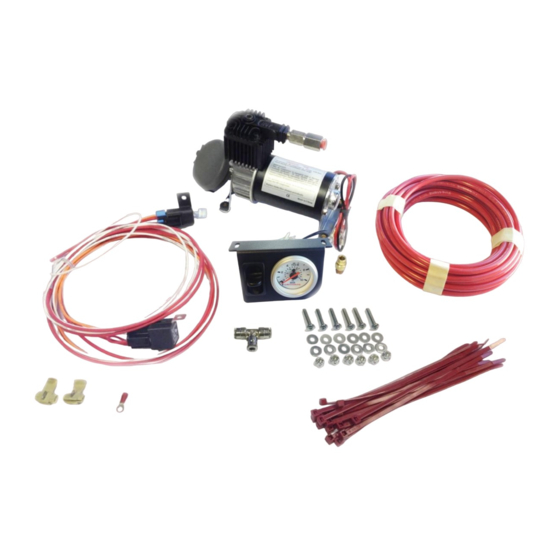
47/13 Revision 2 Kit Contents DIAGRAM... -
Page 5: Hardware List
47/13 Revision 2 HARDWARE LIST Description Quantity Picture/Description Single Gauge Control Panel Compressor - Standard Duty 1/4" Tubing Cable Ties 1/8" Air Fitting 1/8" to 1/4" Straight fitting Relay Harness T-Piece 10-32" x 1" Machine Screws Mounting Compressor and Gauge 10-32"... -
Page 6: Step By Step Installation
47/13 Revision 2 Step by Step Installation Step 1: Locating the mounting area for the Gauge Select a mounting surface under the dash of your vehicle or other protected location. Mark a 5mm (3/16") diameter hole at each of the mounting points, use the air Control Panel as a template for marking the holes. -
Page 7: Step 4: Routing The Air Line Tubing To The Gauge
47/13 Revision 2 Step 4: Routing the Air Line tubing to the Gauge Cut a piece of air line tubing that will reach from the Control Panel to the Compressor. SIDE VIEW OF CONTROL PANEL Make the cut as square as possible. A hole may need to be drilled in the fire wall to enable the air line to pass through the fire wall to the Compressor. -
Page 8: Step 6: Attaching The Air Control Panel To The Dash
47/13 Revision 2 Step 6: Attaching the Air Control Panel to the Dash Place the air control panel on the dash where the holes were drilled in Step 1. Using the 10-32 machine screws, nuts, and washers provided in the kit, attach the air control panel to the dash or other appropriate surface. -
Page 9: Step 8: Test The System
47/13 Revision 2 Step 8: Test the System With the air accessory kit and Drive-Rite suspension products installed, you are ready to test the system. Re-connect the battery. Turn on the ignition. Push the paddle switch up and the compressor will turn on, supplying air pressure to the air springs. The gauge should read how much air pressure is in the air springs. -
Page 10: Notes
47/13 Revision 2 Notes... - Page 11 47/13 Revision 2...
- Page 12 47/13 Revision 2 Unit 626 Kilshane Avenue, North West Business Park, Ballycoolin, Dublin 15, Ireland Telephone: +353 1 8612 632 Fax: +353 1 8612 647 email:info@driveriteair.com Web: www.driveriteair.com...
Need help?
Do you have a question about the DR.11.012236 and is the answer not in the manual?
Questions and answers