Table of Contents
Advertisement
Quick Links
A
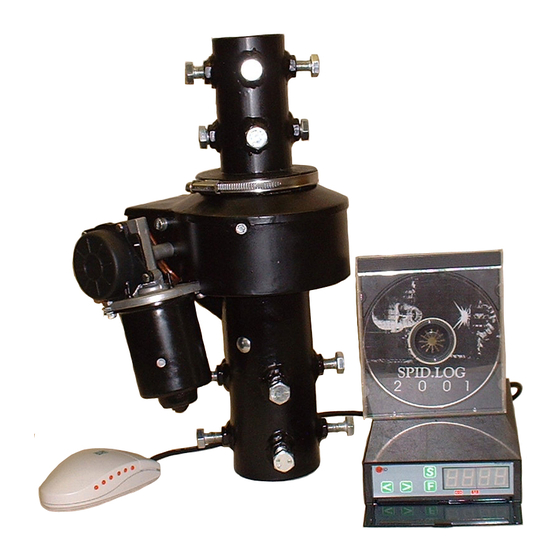
Hy-Gain RAK1C by
lfaSpid
Instruction Manual
This manual is for use with units sold by Hy-Gain as RAK1 and
controller Rot1-Prog ( RAK-1C ). Units sold by others may have
different firmware and may operate from different voltages.
Current version and newer versions of this manual may be found
on the internet at:
http://www.hy-gain.com
or
http://www.alfaspid.com
Last updated on September 5, 2008
A
Copyright
lfaRadio Ltd. 2002-2008
http://alfaspid.com
http://www.hy-gain.com
AlfaSpid_Rotator_AZ_2008-09-05_Manual_MFJ.doc
Advertisement
Table of Contents

Summary of Contents for AlfaSpid Hy-Gain RAK1C
- Page 1 Hy-Gain RAK1C by lfaSpid Instruction Manual This manual is for use with units sold by Hy-Gain as RAK1 and controller Rot1-Prog ( RAK-1C ). Units sold by others may have different firmware and may operate from different voltages. Current version and newer versions of this manual may be found on the internet at: http://www.hy-gain.com...
-
Page 2: Table Of Contents
Rotator RAK1 http://Alfaspid.com http://www.hy-gain.com Page 2 Table of Contents Introduction .................... 4 Shipping Contents.................. 4 Technical Data ..................4 Control Panel ..................5 Rear Panel ..................... 6 Installation ....................7 Bench Testing..................8 Resetting the Controller ................. 9 Controller Operation................10 Function Mode.................. -
Page 3: Introduction
Rotation Speed ............120 sec (12 V) / 60 sec (24 V) Turning Torque (in lbs) ........... 1400 (12 V) / 1740 (24 V) Braking Torque (in lbs) ................> 14,000 lfaSpid Rotator RAK1 http://Alfaspid.com http://www.hy-gain.com Page 3 of 21 Copyright... -
Page 4: Control Panel
Rotator RAK1 http://Alfaspid.com http://www.hy-gain.com Page 4 Control Panel Front Panel Front Panel Front Panel Buttons -Left (Decrease) -Right (Increase) -Setup -Function Indicators -Overlap -Not currently used 7 segment 4-digit display - Multifunction display Page 4 lfaSpid Rotator RAK1 http://Alfaspid.com http://www.hy-gain.com Copyright lfaRadio Ltd. -
Page 5: Rear Panel
- Power Cord - Power Switch - Terminal Strip 4 Pin Connector -DB-9 connector (female) -DB-9 connector (male) Female for CPU / RS232 Male for lfaSpid Mouse lfaSpid Rotator RAK1 http://Alfaspid.com http://www.hy-gain.com Page 5 of 21 Copyright lfaRadio Ltd. 2002-2008... -
Page 6: Installation
Rotator RAK1 http://Alfaspid.com http://www.hy-gain.com Page 6 Installation Wiring Connections The rotator unit must be wired to the control unit with 4-wire cable. The gauge of the 4-wire cable to connect the control unit to the rotator depends upon the distance between rotator and controller. -
Page 7: Bench Testing
If the motor turns for a few seconds and then you hear the relay in the control box drop out, the motor has either stalled or there is a problem in the impulse sense wiring. lfaSpid Rotator RAK1 http://Alfaspid.com http://www.hy-gain.com Page 7 of 21 Copyright lfaRadio Ltd. -
Page 8: Resetting The Controller
Rotator RAK1 http://Alfaspid.com http://www.hy-gain.com Page 8 Resetting the Controller Since there are no mechanical limits in the rotator, it may be installed with the antenna pointing in any direction. There is no reason to locate “TRUE NORTH” until you are ready to calibrate the control box. Use the controller to position the antenna to physically point north, then reset the controller as follows: Turn the unit OFF. -
Page 9: Controller Operation
The “0” (Zero) in the - Half Auto Mode displays to the left will be replaced by your actual beam - Auto Mode heading - Preset Mode lfaSpid Rotator RAK1 http://Alfaspid.com http://www.hy-gain.com Page 9 of 21 Copyright lfaRadio Ltd. 2002-2008... -
Page 10: Setup Mode
Rotator RAK1 http://Alfaspid.com http://www.hy-gain.com Page 10 - Normal Operations Mode In Normal Operations Mode, the buttons cause rotation as long as the buttons are pressed. Pressing while in normal operations mode will take you to setup mode. - Half Auto Mode... -
Page 11: Programmable Low Limit
By reducing this value, the maximum clockwise rotation travel can be restricted. Use the buttons adjust the value. These limits can be used when side mounting the rotor to keep the antenna from colliding with the tower. lfaSpid Rotator RAK1 http://Alfaspid.com http://www.hy-gain.com Page 11 of 21 Copyright lfaRadio Ltd. 2002-2008... - Page 12 Rotator RAK1 http://Alfaspid.com http://www.hy-gain.com Page 12 - Programmable Low Limit The Programmable Low Limit is a user adjustable counter-clockwise travel limit value. By increasing this value, the minimum counter-clockwise rotation travel can be restricted. Use the buttons adjust the value.
- Page 13 LED readout to match the known heading, rather than having to turn back to North and reset the controller. lfaSpid Rotator RAK1 http://Alfaspid.com http://www.hy-gain.com Page 13 of 21 Copyright lfaRadio Ltd.
-
Page 14: Mouse Controller
Rotator RAK1 http://Alfaspid.com http://www.hy-gain.com Page 14 Mouse Controller (Optional) The optional mouse controller (not a computer mouse) allows easy desktop access to the most commonly used front panel controls. These buttons are functionally equivalent to the corresponding front panel controls. - Page 15 There should be no conductivity between 1 and 3 or 1 and 4, or between 2 and 3 or 2 and 4 All lines should have no conductivity to ground. lfaSpid Rotator RAK1 http://Alfaspid.com http://www.hy-gain.com Page 15 of 21 Copyright...
- Page 16 Rotator RAK1 http://Alfaspid.com http://www.hy-gain.com Page 16 Be careful not to over wind your coax with the next test, as there will be no protection from over turning. Find a small 12 volts supply which will deliver 3 to 4 amps. ( a small 12 Volt battery will work just fine ) To confirm that the motor runs you may connect 12 volts D.C.
- Page 17 Typically 36 to 50 volts at 3-5 amps should be quite adequate. These DC motors are quite tolerant on their voltage ratings. Relay Board Schematic lfaSpid Rotator RAK1 http://Alfaspid.com http://www.hy-gain.com Page 17 of 21 Copyright lfaRadio Ltd.
- Page 18 Rotator RAK1 http://Alfaspid.com http://www.hy-gain.com Page 18 Relays chosen should be suitable for the proper coil voltage as well as appropriate current carrying capability. A relay capable of 5 to 10 amps DC is adequate. The diode in series with Relay K1 is any general purpose 1 amp style such as the 1N400x series.
- Page 19 NOTE: There is a two to five day response time for all technical support emails. If this is not fast enough for you, please call us on our technical support lines listed above. lfaSpid Rotator RAK1 http://Alfaspid.com http://www.hy-gain.com Page 19 of 21 Copyright lfaRadio Ltd.
- Page 20 Rotator RAK1 http://Alfaspid.com http://www.hy-gain.com Page 20 NOTES: _________________________________________________________ _________________________________________________________ _________________________________________________________ _________________________________________________________ _________________________________________________________ _________________________________________________________ _________________________________________________________ _________________________________________________________ _________________________________________________________ _________________________________________________________ _________________________________________________________ _________________________________________________________ _________________________________________________________ _________________________________________________________ _________________________________________________________ Page 20 lfaSpid Rotator RAK1 http://Alfaspid.com http://www.hy-gain.com Copyright lfaRadio Ltd. 2002-2008...
- Page 21 Blue 0 to 180 is the dot (not flashing) PH over travel (Right 180 side of diagram) Red 0 to 180 is the dot (flashing) PL over travel (Left 180 side of diagram) lfaSpid Rotator RAK1 http://Alfaspid.com http://www.hy-gain.com Page 21 of 21 Copyright lfaRadio Ltd.
Need help?
Do you have a question about the Hy-Gain RAK1C and is the answer not in the manual?
Questions and answers