Table of Contents
Advertisement
Quick Links
Advertisement
Table of Contents

Summary of Contents for BVV Mercurius MK-V
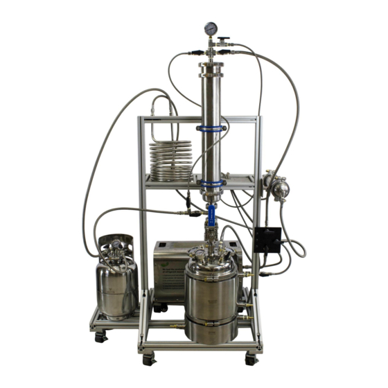
- Page 1 Mercurius MK-V Active Closed Loop Extractor User Manual...
-
Page 2: Table Of Contents
Table of Contents • Introduction:……………………………………………………………………………………………………………………………………………………….3 General Uses and Extraction Information……………………………………………………………………………………………..3 General Safety Information…………………………………………………………………………………………………………………..3 iii. Preparing to Extract……………………………………………………………………………………………………………………………………..4 Manipulating Thermals…………………………………………………………………………………………………….…………………..4 a. Using Circulatory Pumps b. Using Immersion Heater Chilling Options Controls and Components…….…………………………………………………………………………………………………...6 a. Valve/Hose Layout b. Active Recovery Set-up • Startup and Operation:……………………………………………………………………………………………………………………………………….6 Pre-Run Procedure/Testing……………………………………………………………………………………………………………………..7 Utilizing Solvent Evaporative Cooling……………………………………………………………………………………………………………………. -
Page 3: Introduction
Introduction: The Mercurius Active closed loop is intended to perform hydrocarbon botanical extraction within a sealed system. Rack mounting provides ease of work, eliminating heavy lifting associated with operating large capacity units of the past. Using a combination of jacketed columns, condensers, and solvent evaporation, temperatures can be controlled throughout the system to ensure the highest clarity extract is achieved. -
Page 4: Preparing To Extract
Preparing to Extract Before you begin, you are going to want to make sure you have the necessary supplies to run the unit. Here is a list of some things that will be needed to operate the unit. ▪ Tools (various wrenches/sockets) ▪... - Page 5 vacuum on itself. If temperatures will not allow this negative pressure, the pump will always be fighting this opposing pressure. If you refer to (fig. 1), you can see that solvent pressure is directly related to its temperature. As the solvent increases in temperature above the boiling point (fig.2), pressure will increase.
-
Page 6: Using Circulatory Pumps
a. Using Circulatory Pumps The Mercurius Active system uses a jacketed collection base. In order to manipulate thermals within the collection, a chiller or circulation pump and heat/cold bath is required. It is recommended to use a dry ice and propelyne glycol bath for the cold end, and a water bath with an immersion heater for the warm. -
Page 7: Valve/Hose Layout
a. Valve/Hose Layout The valve layout and hose configuration is listed in the diagram below. Hoses diameters are listed below. b. Active Recovery Set-up The Mercurius Active closed loop extractor comes standard with an active recovery set up. This consists of a molecular sieve, recovery pump, condensing coil, and LP tank. -
Page 8: Startup And Operation
The recovery pump is used during recovery to add a mechanical assistance to passive solvent recovery. This is used to help regulate pressures and speed up recovery. The recovery pump also features a coil bypass which is used to manipulate pressure and temperature of the material column. The final stage of the active recovery system is a condensing coil. -
Page 9: Utilizing Solvent Evaporative Cooling
After unit is fully packed and assembled, attach nitrogen cylinder to manifold and perform pre-run pressure testing. Every time you assemble your Mercurius Active system, it is vital that the system is pressure tested to 90 PSI with nitrogen gas. This ensures all clamps/gasket and hose connections are sealed. - Page 10 The diagram above (fig. 4) shows a two-step flow of how this is performed. Red blocks indicate closed valves, green signifies open. During path 1, valves numbered 2 are closed, vice versa. First start by opening the liquid port on LP tank, then follow path one. Use the top flood input valve to gently feather solvent into the material column.
-
Page 11: Adding Solvent To System
Adding Solvent to the System Connect LP tank to the solvent input manifold (please refer to assembly diagram) using the short ¼” SS line. It is recommended to connect the liquid valve (red handle) to the manifold. This port contains a dip-tube, so the cylinder must be upright to empty liquid solvent. -
Page 12: Top Flood Input
b) Top Flood Input: After the bottom fill overflow valve has been closed, switch the solvent input manifold to the top flood position(valve handles both in vertical positioning) then open the inline ball valve. Extract bearing solvent will flow from the material column to the collection base. Leave the ball valve open until solvent flow ends. To aid solvent movement to the collection base, it is recommended to recirculate a chilled fluid through the jacket. -
Page 13: Utilizing The Hot Vapor Loop
Utilizing Hot Vapor Loop: The Mercurius Active system is set up to use a hot vapor loop to assist in clearing and recovering the material column. This is achieved by utilizing the heat created by the recovery pump, then bypassing the condensing coil to push hot vapors to the top of the material column. As vapor initially enters the material column, the inline ball valve is to be closed. -
Page 14: Recovery
Recovery: Recovery is the distillation of the solvent in the collection chamber. By distilling, the impurities in the gas will be left behind (in this case, extract) as the gas moves to the LP tank. In order to efficiently recover without damaging the extract, a few factors must be acknowledged. First, we need to note the boiling point of the solvent. -
Page 15: Collection Base Recovery
It is recommended to start recovery on the column first. Make sure coil is submerged in a dry ice slurry. It is important to get the coil as cold as possible during the recovery. If dry ice is not available, an ice bath will work, however recovery times will be significantly increased. -
Page 16: When Is Recovery Finished
recover into a vacuum. This ensures that solvent vapors do not enter the work space when opening the collection base. During this recovery, it is important to monitor temperatures of the coil bath and the heat bath. Add more dry ice as needed to maintain temperature. -
Page 17: Removing The Extract
Removing the Extract: After removing the collection base from the system, it is time to remove the extract. It is important that the utensil used to remove the extract is chemically compatible with the solvent used. A PTFE scraper is recommended.
Need help?
Do you have a question about the Mercurius MK-V and is the answer not in the manual?
Questions and answers