Table of Contents
Advertisement
Quick Links
Technical Information – Date 05.02.2013
LVB Control Unit
LVB Control Unit
LVB Control Unit
LVB Control Unit
Features
Features
Features
Features
The LVB control unit has the following features:
One transmitter/receiver set can be
•
connected.
Relative switching threshold for reliable object
•
recognition.
Increased safety: safe shut down on contact
•
bonding and no blanking of defect beams.
Floating relay contacts.
•
General description
General description
General description
General description
The device switches when one or more beams are
interrupted.
The output relays have positively driven contacts
(2xreverser), each with one break contact lead back to
a digital input. That ensures the detection of a failure
(„contact did not open") of the brought out normally
open contact. A watchdog unit cuts off the relays at a
failure of the microcontroller.
DUOmetric AG
DUOmetric AG
DUOmetric AG
DUOmetric AG
Weberstr. 8
D - 86836 Lagerlechfeld / Germany
Tel: +49-8232-95979-0
Fax: +49-8232-95979-29
www.duometric.de
Email: support@duometric.de
Advertisement
Table of Contents

Summary of Contents for DUOmetric LVB
-
Page 1: Features
LVB Control Unit LVB Control Unit LVB Control Unit Features Features Features Features The LVB control unit has the following features: One transmitter/receiver set can be • connected. Relative switching threshold for reliable object • recognition. Increased safety: safe shut down on contact •... -
Page 2: Table Of Contents
Circuit board view ......................7 LVB ..........................7 LVB-24V ........................7 DIP-Switch ........................8 Pin assignments LVB-24V .................... 8 Connecting the profiles ....................8 Mounting Instructions for Light Grid Profiles ..............9 Important notes concerning usage and handling ............10 Conformity ........................ -
Page 3: Extended Functionality
Technical Information Extended functionality Extended functionality Extended functionality Extended functionality If necessary your technical support can change parametrisation or do additional diagnosis by using the serial interface. The following functions are disabled on delivery status, but can be enabled by parametrisation: Auto blanking Auto blanking... -
Page 4: Self Calibration
Technical Information Self calibration Self calibration Self calibration Self calibration On self calibration the controller set up the correct gain for the connected light grid set, determines the profile length and executes an error test. During self calibration the monitoring area has to be uninterrupted (Exception: see automatic blanking). Procedure: Procedure: Procedure:... -
Page 5: Leds
LEDs LEDs The LVB indicates operational errors and faults via the eight adjacent LEDs RX, TX, A… F. If the status is normal, LEDs C, D, E, F indicate the signal strength. Please note that the error cannot be localized with 100 percent accuracy. The LEDs only provide you with a good idea of where to start looking. -
Page 6: Initial Operation
Set DIP-3 to „off“ to complete self calibration. 6. Verify that the light grid is working correct in the entire monitoring area. 7. Screw the top on the housing in its place again. 8. Screw in the fittings tight. Version LVB Page 6 of 12... -
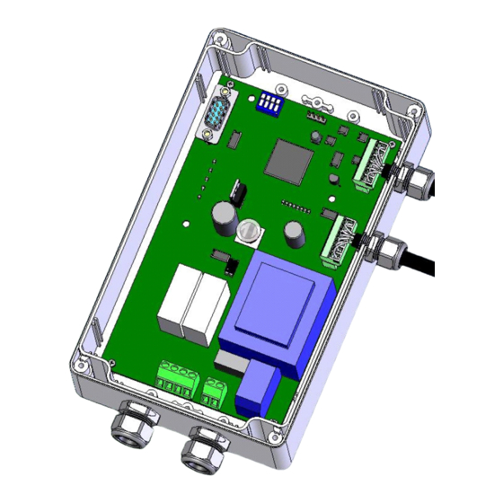
Page 7: Circuit Board View
Technical Information Circuit board view Circuit board view Circuit board view Circuit board view LVB- - - - 24V Page 7 of 12... -
Page 8: Dip-Switch
DIP 2: ON Command mode DIP 3: ON Self-calibration when power on the device DIP 4 For special use Pin assignments LVB Pin assignments LVB Pin assignments LVB Pin assignments LVB- - - - 24V Terminal Des. Comment / Function +24 Vdc Minus 7-11... -
Page 9: Mounting Instructions For Light Grid Profiles
Technical Information Mounting Instructions for Light Mounting Instructions for Light Mounting Instructions for Light Mounting Instructions for Light Grid Profiles Grid Profiles Grid Profiles Grid Profiles • Disassembling of the plug components is not necessary. • Profiles must be off-circuit when connecting or disconnecting the power supply. -
Page 10: Important Notes Concerning Usage And Handling
Technical Information • Danger from reflective surfaces: Reflective surfaces in the area around the light curtain must be avoided. Otherwise obstructions will not be detected. • Avoid optical sensors from mutually affecting each other (e.g., other light curtains, light barriers) Important notes concerning usage and handling Important notes concerning usage and handling Important notes concerning usage and handling... -
Page 11: Technical Data
500 beams (diagonal beams counted) Cycle time Depends on range and parameter definition from approx. 80µs/beam. Power supply 230 Vac (+5%/-10%) LVB-24V 24 (19..30) Vdc (grounded power supply) Power consumption 10VA, approx. 8.5 Watt Relay contacts Closed while no beam is interrupted (standard) Switching current min./max. -
Page 12: Enclosure Dimensions
Technical Information Enclosure Enclosure Enclosure Enclosure dimensions dimensions dimensions dimensions Dimensions in mm. Page 12 of 12...
Need help?
Do you have a question about the LVB and is the answer not in the manual?
Questions and answers