
Summary of Contents for Tynemouth MINI PET 40/80
- Page 2 Tynemouth MINI PET 40/80 www.tynemouthsoftware.co.uk V1.82...
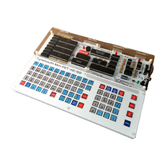
- Page 3 Tynemouth MINI PET 40/80 TYNEMOUTH MINI PET 40/80 KIT USER MANUAL PARTS LIST CAPACITORS – ALL RATED 16V OR HIGHER 2 x 22pF axial (usually marked 220 or 22J) 30 x 100nF axial (usually marked 100n or 104) 4 x 1µF axial (usually marked 1u0 or 105) 1 x 100µF...
- Page 4 Tynemouth MINI PET 40/80 CONNECTORS / SWITCHES / SOUNDER 4 x standard tactile switch 12x12mm + keycaps (e.g. Omron B3F-4055) 73 x light touch tactile switch 12x12mm + keycaps (e.g. Omron B3F-4050) 1 x Piezo AC transducer (not a buzzer or any sounder that has internal circuitry)
- Page 5 Tynemouth MINI PET 40/80 PCB LAYOUT www.tynemouthsoftware.co.uk V1.82...
- Page 6 Tynemouth MINI PET 40/80 DIP SWITCHES The recommended settings for the DIP switches are highlighted in green, all switches off. ROM SETTINGS The Mini PET can run a selection of ROM sets. Commodore ROMs used under license from Amiga Corporation.
- Page 7 Uppercase / Symbols 40/80 COLUMNS The Mini PET 40/80 can generate a 40 column or an 80 column screen. This is supported on any of its video outputs, although readability of 80 columns may be limited on smaller screens. The Mini PET starts in 40 column mode, and the 40/80 button on the keyboard can be used to change mode.
- Page 8 Tynemouth MINI PET 40/80 RGBI COLOUR Although the Mini PET is a monochrome machine, the RGBI output can be configured as white on black or green on black using switch 10. Switch 10 has no effect on other modes. Switch 10...
- Page 9 Tynemouth MINI PET 40/80 DOS WEDGE The DOS Wedge gives a number of additional shortcut commands to access a disk drive, and is particularly suited to use with the SD2PET SD card disk drive. THIS IS BUILT IN TO THE MINI PET BASIC 4.1 ROMS, AND IS AUTOMATICALLY ACTIVATED AT POWER ON, THERE IS NO NEED TO LOAD FROM DISK OR USE A SYS COMMAND.
- Page 10 Tynemouth MINI PET 40/80 FILE BROWSER A file browser is built into the MINI PET BASIC 4.1 ROM images. This is particularly suited to use with the SD2PET SD card disk drive. This can be activated by pressing the NMI / MENU button on the bottom right of the keyboard.
- Page 11 Tynemouth MINI PET 40/80 MACHINE LANGUAGE MONITOR All BASIC versions apart from 1 have a built in machine language monitor. This is activated by the break handler, so is called at any point the BRK instruction is executed. This is code 00, so the monitor can be launched by jumping to anywhere there is a 00 stored in memory.
- Page 12 Tynemouth MINI PET 40/80 SCHEMATICS AND THEORY OF OPERATION 6502 CPU The heart of the Mini PET is the 6502 processor. Here a WDC W65C02S is used. This is a modern version of the NMOS 6502. It is not pin compatible and the read / write timing differs, so an original chip cannot be used with the Mini PET (nor can anything that would plug into the CPU socket).
- Page 13 Tynemouth MINI PET 40/80 ADDRESS DECODING The ROM chip provides ROM in two ranges, from 9000 through to E7FF and E900 through to FFFF. This is implemented here by decoding the video RAM (8000-8FFF) and the IO cut out (E800-E8FF) and selecting the ROM anywhere that is not RAM, video RAM or IO.
- Page 14 Tynemouth MINI PET 40/80 INPUT AND OUTPUT USERPORT The userport is provided by a W65C22N VIA (a modern version of the NMOS 6522). This chip also provides further datasette and IEEE-488 signals. The PET userport is not compatible with Commodore 64 or VIC20 Userport peripherals.
- Page 15 Tynemouth MINI PET 40/80 IEEE-488 PORT The IEEE-488 port signals are mainly provided by A W65C21N chip as the PIA#1 (the W65C21N being a modern version of the NMOS 6520). The remaining signals are provided by PIA#2 and the VIA.
- Page 16 Tynemouth MINI PET 40/80 DATASETTES The Mini PET provides two datasette connections, driven by identical circuitry. Previous designs used a simple voltage regulator based on a Zener diode and a pass transistor. In the PET 2001, a 1.5K resistor and 7.2V Zener diode form a simple voltage regulator, buffered by a Darlington transistor pair.
- Page 17 Tynemouth MINI PET 40/80 The output voltage can be set using the ratio of the two feedback resistors, according to the following equation: �� �� = �� { 1 + ������ ������ �� is an internal 1.235V reference, and R is using the recommended value of 100KΩ.
- Page 18 Tynemouth MINI PET 40/80 KEYBOARD MATRIX The keyboard matrix matches that of the PET Chiclet keyboard, with 10 rows and 8 columns There are four additional buttons on the Mini PET 4080 keyboard which are not part of the normal keyboard matrix.
- Page 19 Tynemouth MINI PET 40/80 40/80 BUTTON The 40/80 button is used to switch between 40 column and 80 column video modes. This has the same debouncing circuit as the NMI button, but without the second stage of inversion. This gives a clean positive pulse when the 40/80 button is pressed.
- Page 20 Tynemouth MINI PET 40/80 POWER BUTTON The power button again uses the same 40106 debouncing circuit and 4013 flip flop as the 40/80 switch above. In addition, a second RC circuit is used to generate a power on positive pulse to the set pin. This ensures the 5V regulators are always in standby when power is applied.
- Page 21 Tynemouth MINI PET 40/80 VIDEO The video circuitry of the Mini PET is very different to that of an original PET, but implements the same functionality as a 2001 or closer to a 2001N PET. 1K-2K of video RAM is used to store a screen made up of one byte for each of 40 or 80 x 25 characters.
- Page 22 Tynemouth MINI PET 40/80 PIXEL CLOCK When a character is selected in the character ROM, the 8 bits of pixel data are latched into a shift register and clocked out by the pixel clock. The speed of this clock is selected using the 257, 8 MHz for 40 column modes, or 16 MHz for 80 column modes.
- Page 23 Tynemouth MINI PET 40/80 VIDEO OUTPUTS The Mini PET supports multiple types of monitor. The PET monitors and CGA/MDA/RGBI types are fed with horizontal and vertical sync and video data. The polarities and timing of these vary with the monitor type.
- Page 24 Tynemouth MINI PET 40/80 OPTIONS The video mode is selected via a 10 way DIP switch, which also selects one of four system ROMs and one of four character ROMs and some other options. The switch options are detailed in a separate section, but in brief: ...
- Page 25 Tynemouth MINI PET 40/80 VIDEO TIMINGS The different monitor types have various different frame and line timings, as well as changes to sync polarity and image positioning. PET Monitor Composite Video RGBI HSync VSync Video Text Frame Line NTSC (240p60)
- Page 26 Tynemouth MINI PET 40/80 PINOUTS All connectors are viewed from what would be the outside of the PET, pin 1 to the right as you look from the keyboard. The grey lines indicate the slots in the edge connector or pin gips in the pin headers.
- Page 27 Tynemouth MINI PET 40/80 DATASETTES The PET supports two datasettes, each of which uses the same datasette edge connector as the VIC20 and Commodore 64, so you can use a C2N or 1530 datasette to load or save programs. Each drive is also wired to a 7 pin 0.1”...
- Page 28 Tynemouth MINI PET 40/80 9 WAY D MONITOR The 9 way connector is used to connect an MDA or Hercules monitor, a CGA monitor, or an RGBI monitor such as a Commodore 1084S or 1901. When a colour monitor is used, the signals sent to the port are selected based switch 10.
Need help?
Do you have a question about the MINI PET 40/80 and is the answer not in the manual?
Questions and answers