Table of Contents
Advertisement
Available languages
Available languages
Quick Links
Advertisement
Chapters
Table of Contents

Summary of Contents for electrify home HomeStation EC2R040JPA10-00
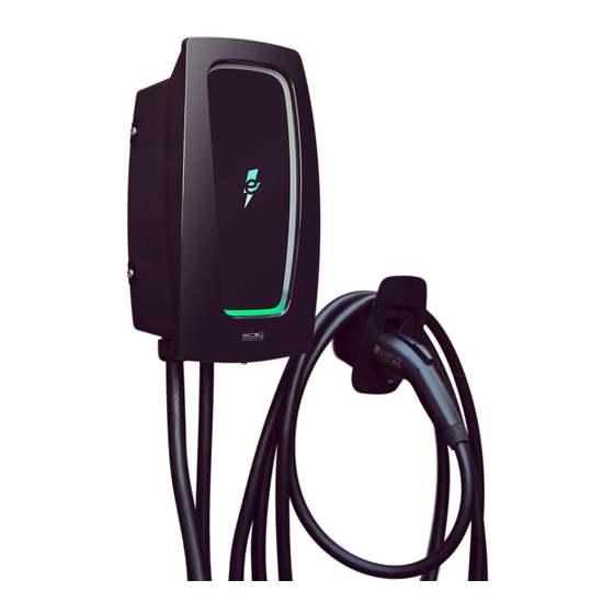
- Page 1 HomeStation Level 2 Charger I N S TA L L AT I O N A N D O P E R AT I O N M A N U A L HomeStation Chargeur de niveau 2 G U I D E D ' I N S TA L L AT I O N E T D ' U T I L I S AT I O N Version: 2.0.1 Issue Date: March 10, 2021 / Date de publication : 10 mars 2021...
- Page 2 e l e c t r i f y h o m e Customer Support / Service à la clientèle : 833-531-3226...
-
Page 3: Table Of Contents
Contents Information Operating Instructions Copyright Charger Status 2 About This Document Status Indicator 3 Intended Use 2 Indicator Definition 4 Charger—Intended Use 3 Understanding Status 5 Important Safety Instructions Indicator Patterns 6 EMC Compliance Statement: 4 Faults FCC Part 15, Subpart B, Class B Troubleshooting Product Overview Specifications... -
Page 4: Information
Information Copyright Important Safety Instructions R E A D A L L T H E I N S T R U C T I O N S B E F O R E I N S TA L L I N G , O P E R AT I N G , Copyright ©... -
Page 5: Emc Compliance Statement
Important Safety Instructions (continued) contain the latest changes to the product’s specifications or processes described herein. For the most up-to-date information, please visit electrifyhome.ca. contact Electrify America or Electrify Canada. Electrify America and Electrify Canada are not responsible for any damages that may occur resulting from EMC Compliance Statement: custom installations or operations that are not described in this document. -
Page 6: Product Overview
Product Overview N O . I T E M N O . I T E M LED Ring Cable Holster Cosmetic Cover Vehicle Connector Plug Mounting Bracket Middle Cover Body H O M E S T A T I O N L E V E L 2 C H A R G E R... -
Page 7: Included Components List
Included Components List Recommended Tools TOOLS FOR PLUG - IN IN STALL ATION 1. Level 2. Pencil 3. Electric Drill 4. Phillips-Head Screwdriver TOOLS FOR HARDWIRED IN STALL ATION Charger Mounting bracket x 1 Mounting template x 1 1. Level 2. -
Page 8: Installation Instructions
Installation Instructions Before Installing We recommend that a certified electrician perform all in-home installations, 1. Install the holster—measured from the and this charger should not be installed in any circumstances without first bottom between 31.5" (80 cm) and consulting with an electrician familiar with your home, its electrical panel and 43.3"... -
Page 9: Installation Steps
Installation Steps 5. Once the mounting bracket is installed, place the charger into the bracket and secure the charger to the bracket using the 4 supplied T30 Torx screws. This product must have a proper electrical ground connection. Proper electrical grounding reduces the risk of electric shock. -
Page 10: Installation With Hardwiring
Installation with Hardwiring These installation instructions are intended for certified electricians. Only REMOVE TH E PLUG CAB LE qualified, certified electricians should hardwire the charger. In addition 1. Remove the plug cable by loosening the 3 center screws (shown as L1, L2, and to the charger installation instructions, follow all federal, provincial, and local PE) in the terminal block. - Page 11 2. Crimp insulated wire ferrules onto each supply power wire, including ground. Follow the ferrule manufacturer’s instructions for crimping the ferrules onto each wire. RE AT TACH TH E COVER 1. Secure the middle cover with the screws removed (as in the previous steps). 2.
-
Page 12: Operating Instructions
Operating Instructions Insert the vehicle connector into the charging Once the charger is plugged into the vehicle, the port on your electric vehicle. The charger will charger will begin flashing blue as it links with light up green when a connection is detected. the vehicle. - Page 13 Charging is complete when the charger turns Press the thumb lever on the vehicle connector green once more. to disconnect from the vehicle. I N S T A L L A T I O N A N D O P E R A T I O N M A N U A L...
-
Page 14: Charger Status
Charger Status If you are experiencing difficulty charging, a fault indicator light, or any other issue using the charger, please see the Troubleshooting section for assistance. If the issue persists, please contact Electrify Canada Customer Support at 833-531-3226. Status Indicator Indicator Definition The charger is equipped with an integrated LED ring to allow for clear communication of the charger’s status. -
Page 15: Understanding Status Indicator Patterns
Understanding Status Indicator Patterns Faults L E D C O L O R I N D I C AT O R D E S C R I P T I O N L E D I N D I C AT O R D E S C R I P T I O N No color Red, 1 flash... -
Page 16: Troubleshooting
Troubleshooting S I T U AT I O N C A U S E A C T I O N Ask a certified electrician to check that the power input is connected correctly and the power is within operating range of the unit. Status indicator does Charger is not receiving power. -
Page 17: Specifications
Specifications Model EC2R040JPA10-00 Communication Protocol CPP 1.6+ JSON Compliant Measurements (H x W x D) 15.75" x 8.66" x 6.75" (approx.) AC Fault Monitor GFCI Integrated (20mA CCID for AC) Cable Length 24 Feet 50A Circuit Breaker (not provided with Short Circuit/ unit, no GFCI) for 40 A Output (Refer to Overload Protection... -
Page 18: Moving, Transportation, And Storage
Moving, Transportation, Warranty and Storage Customer Support can provide more information on the terms of the warranty. However, the following cases are not covered by the warranty: Improper moving or storage of this device may result in a A. Defects or damage caused by any failure to install, operate, or care for WA R N I N G : risk of fire or electric shock. - Page 19 Table des matières Information Instructions d’utilisation Droit d’auteur État du chargeur 2 À propos de ce document Voyant d’état 3 Utilisation prévue 2 Définition du voyant 4 Chargeur—Utilisation prévue 3 Compréhension des 5 Instructions de sécurité importantes 20 schémas du voyant d’état 6 Déclaration de conformité...
-
Page 20: Information
Information Droit d’auteur Instructions de sécurité importantes Droit d’auteur © Electrify Canada LP, 2021. Tous droits réservés. Ce document LISEZ TOUTES LES INSTRUCTIONS AVANT L’INSTALLATION, L’UTILISATION OU est protégé par le droit d’auteur. Il est interdit de le modifier, de L’ENTRETIEN DE CE PRODUIT. -
Page 21: Déclaration De Conformité
Instructions de sécurité importantes (suite) Déclaration de conformité électromagnétique : IC, CAN ICES-002(B) / NMB-002(B) dommages découlant d’installations sur mesure ou d’utilisations qui ne sont pas décrites dans le présent document. IC ID: 26750-R040JPA1000 10. Équipement de protection individuelle : Lors de l’installation ou de l’entretien de 1. -
Page 22: Aperçu Du Produit
Aperçu du produit A R T I C L E A R T I C L E Anneau à DEL Étui pour câble Couvercle décoratif Connecteur du véhicule Fiche Support de montage Couvercle du centre Boîtier B O R N E D O M E S T I Q U E C H A R G E U R D E N I V E A U 2... -
Page 23: Liste Des Composants Inclus
Liste des composants inclus Outils recommandés OUTILS POU R L’IN STALL ATION EN FICHAB LE 1. Niveau 2. Crayon 3. Perceuse électrique 4. Tournevis cruciforme OUTILS POU R L’IN STALL ATION CÂB LÉE Chargeur Support de montage x 1 Gabarit de montage x 1 1. -
Page 24: Instructions D'installation
Instructions d’installation Avant l’installation Nous recommandons qu’un électricien certifié effectue toutes les 1. Installer l’étui de façon à ce que sa partie installations à domicile, et ce chargeur ne doit en aucun cas être installé sans inférieure se situe entre 80 cm (31,5 po) consulter au préalable un électricien connaissant bien votre maison, son et 110 cm (43,3 po) au-dessus du sol. -
Page 25: Étapes D'installation
Étapes d’installation 5. Une fois le support de montage installé, placer le chargeur dans le support et le fixer à l’aide des quatre vis Torx T30 fournies. Ce produit doit disposer d’une connexion à la terre appropriée. Une mise à la terre correcte réduit le risque de choc électrique. -
Page 26: Installation Câblée
Installation câblée Les présentes instructions d’installation sont destinées aux électriciens RETIRER LE CÂBLE DE LA FICHE certifiés. Seuls des électriciens qualifiés et certifiés doivent effectuer le 1. Pour retirer le câble de la fiche, dévisser les trois vis du centre (L1, L2 et PE) dans câblage du chargeur. - Page 27 2. Sertir les embouts isolés sur chaque fil d’alimentation, y compris celui de mise à COURANT NOMINAL COURANT NOMINAL MAXIMUM MAXIMUM la terre. Suivre les instructions du fabricant de la virole pour sertir les viroles sur chaque fil. REMETTRE LE COUVERCLE EN PLACE 1.
-
Page 28: Instructions D'utilisation
Instructions d’utilisation Brancher le connecteur du véhicule dans le port Lorsque le chargeur est branché dans le véhicule, de recharge de votre véhicule électrique. Le chargeur il clignote en bleu pendant qu’il effectue la liaison avec le s’allume en vert quand un branchement est détecté. véhicule. - Page 29 La recharge est terminée quand le chargeur s’allume Appuyer sur la gâchette de pouce sur le connecteur de nouveau en vert. du véhicule pour le débrancher du véhicule. G U I D E D ’ I N S T A L L A T I O N E T D ’ U T I L I S A T I O N...
-
Page 30: État Du Chargeur
État du chargeur Si vous avez des difficultés à recharger le chargeur, si un voyant lumineux d’erreur s’allume ou si vous avez tout autre problème lié à l’utilisation du chargeur, veuillez consulter la section Dépannage pour obtenir de l’aide. Si le problème persiste, veuillez communiquer avec le service à la clientèle d’Electrify Canada au 833-531-3226. -
Page 31: Compréhension Des Schémas Du Voyant D'état
Compréhension des schémas de voyant d’état Anomalies V O YA N T À D E L D E S C R I P T I O N V O YA N T À D E L D E S C R I P T I O N Aucune couleur Rouge, 1 clignotement Hors tension. -
Page 32: Dépannage
Dépannage S I T U AT I O N C A U S E M E S U R E À P R E N D R E Demander à un électricien certifié de vérifier si l’entrée d’alimentation est bien branchée et si l’alimentation se situe dans la plage de fonctionnement de l’appareil. -
Page 33: Spécifications
Spécifications Modèle EC2R040JPA10-00 Interface utilisateur/IHM Anneau lumineux à DEL Dimensions (hauteur x Sans fil WLAN avec 2,4GHz b/g/n et WPA2 15,75 po x 8,66 po x 6,75 po (environ) largeur x profondeur) Protocole de Conforme OCPP 1.6+ JSON Longueur du câble 24 pieds communication Type d’installation... -
Page 34: Déménagement
Déplacement, transport, Garantie et entreposage Le service à la clientèle peut vous fournir de plus amples renseignements sur les modalités de la garantie. Un déplacement ou un entreposage incorrect de cet appareil Cependant, les cas suivants ne sont pas protégés par la garantie : AVERTISSEMENT : peut entraîner un risque d’incendie ou de choc électrique. - Page 35 e l e c t r i f y h o m e Customer Support / Service à la clientèle : 833-531-3226...
- Page 36 Version: 1.0.5 Issue Date: March 10, 2021 / Date de publication : 10 mars 2021...
Need help?
Do you have a question about the HomeStation EC2R040JPA10-00 and is the answer not in the manual?
Questions and answers