
Related Manuals for TREW 1500 Series

Summary of Contents for TREW 1500 Series
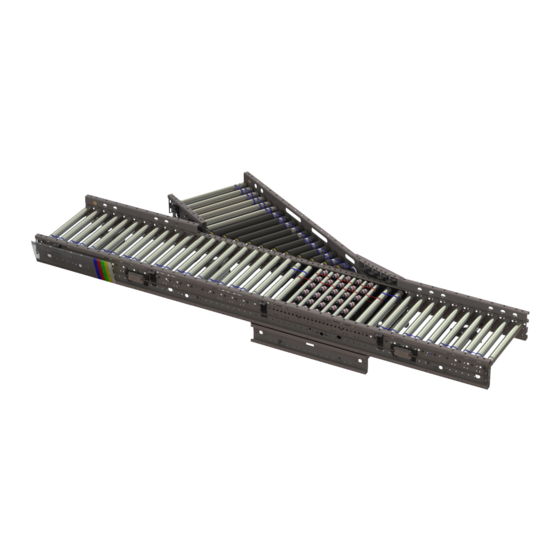
- Page 1 INSTALLATION & MAINTENANCE MANUAL SERIES 1500 24VDC MOTORIZED DRIVER ROLLER HCAT30 POP-UP DIVERT SECTION 1.800.571.8739 poweredbyTREW.com info@trewautomation.com...
-
Page 2: Table Of Contents
www.poweredbyTrew.com 1.800.571.8739 info@trewautomation.com TABLE OF CONTENTS OVERVIEW COMPONENTS HCAT30 Pop-Up Base Types of MDR 2.10 Replacement of MDR Carrier Roller 2.14 2.14 Replacement of Carrier Roller 2.14 Replacement of Carrier Roller for Top Surface Drive Belts (O-Bands) 2.15 Proximity Sensors 2.15 2.15 Proximity Sensor Adjustment... -
Page 3: Overview
www.poweredbyTrew.com 1.800.571.8739 info@trewautomation.com OVERVIEW REV A HCAT30 - Installation and Maintenance Manual... - Page 4 www.poweredbyTrew.com OVERVIEW Theory Of Operation The HCAT30 pop up divert module provides the ability to divert packages off a conveyor system at moderate rates. The HCAT30 is designed to divert packages at a 30 degree angle relative to the main conveyor line, while not stopping the package during the divert process.
-
Page 5: Components
www.poweredbyTrew.com 1.800.571.8739 info@trewautomation.com COMPONENTS REV A HCAT30 - Installation and Maintenance Manual... - Page 6 www.poweredbyTrew.com COMPONENTS Components The HCAT30 is broken down into three sub-assemblies, top surface rollers, pop-up base and lift drive assembly. Assembly of all three sub-assemblies is shown in Figure 1. First two images (2.1) will show components of top surface and lift drive assembly. Third image (2.2) shows the connection point of all three sub-assemblies.
- Page 7 www.poweredbyTrew.com COMPONENTS Figure 1.3 REV A HCAT30 - Installation and Maintenance Manual...
- Page 8 www.poweredbyTrew.com COMPONENTS Figure 1.4 REV A HCAT30 - Installation and Maintenance Manual...
-
Page 9: Hcat30 Pop-Up Base
www.poweredbyTrew.com COMPONENTS HCAT30 Pop-Up Base Figure 2 (2.5) shows the assembly of the pop-up base. The first image shows the components of the carriage and divert wheel. Second and third image shows the components that attach to the sides of the pop-up base plate. Fourth image is the orientation of the rollers. Fifth image is the assembly of the pop-up base. - Page 10 www.poweredbyTrew.com COMPONENTS Figure 2.1 Figure 2.2 REV A HCAT30 - Installation and Maintenance Manual...
- Page 11 www.poweredbyTrew.com COMPONENTS Figure 2.3 Figure 2.4 REV A HCAT30 - Installation and Maintenance Manual...
- Page 12 www.poweredbyTrew.com COMPONENTS Figure 2.5 Figure 2.6 REV A HCAT30 - Installation and Maintenance Manual...
-
Page 13: Types Of Mdr
www.poweredbyTrew.com COMPONENTS Types of MDR There are three types of MDR used in the HCAT30. The three types are the lift drive assembly roller, the divert wheel drive assembly rollers and top surface drive roller. The divert wheel drive assembly rollers drive the pop-up divert wheels. The lift device assembly roller as oblong shape plates welded to each end to allow the mechanism to lift to the desired height. -
Page 14: Replacement Of Mdr
www.poweredbyTrew.com COMPONENTS Replacement of MDR 1 Turn off and Lockout / Tag-out all power to the conveyor section 2 Make sure that the Gear Ratio matches that of the roller that is being replaced. Standard Gear Ratios would include: 12:1, 16:1, 24:1, 36:1, 64:1, and 96:1. This is important if the conveyor system is comprised of more than one speed 3 The replacement roller should include: a Motorized Drive Roller for BF and Gear Ratio... - Page 15 www.poweredbyTrew.com COMPONENTS 5 Utilizing the fold and fan method described above insert the MDR connector into the hex hole and gently pull the cable extending from the motor through 6 Insert the threaded hex shaft into the hex hole. Push the spring loaded idler shaft inwards and line the roller up with the hole.
- Page 16 www.poweredbyTrew.com COMPONENTS 9 Tools required to achieve proper torque can be seen in Figure 6 10 Plug the motor cable into the motor control card 11 Turn on power to the conveyor section These checks must be performed with the power to the conveyor section turned “ON”.
- Page 17 www.poweredbyTrew.com COMPONENTS Proper Torque Gear Ratios Vary. EC110 and EC100: EC310: 30 ft-lbs +/- 5 ft-lbs 50 ft-lbs +/- 5 ft-lbs (40.7 N-M +/- 6 N-M) (67.8 N-m +/- 6 N-m) ITOH: 22.5 ft-lbs +/- 5 ft-lbs (30.5 N-M +/= 6 N-M) REV A HCAT30 - Installation and Maintenance Manual 2.13...
-
Page 18: Carrier Roller
www.poweredbyTrew.com COMPONENTS Carrier Roller The carrier roller is used to take the weight of the product and also distributes the torque generated by the motorized drive rollers via o-belts, chain, timing belts, strip belts, or full-width belts. Generally, no more than nine carrier rollers per motorized drive roller are used in each zone. -
Page 19: Drive Belts (O-Bands)
www.poweredbyTrew.com COMPONENTS Drive Belts (O-Bands) MDR conveyor utilizes drive belts to connect individual rollers together to create a Zone. The drive belts can be O-bands or V belts, depending upon load and speed requirements of the conveyor. Over time the drive belts can exhibit wear. O-bands in particular can wear or stretch, eventually allowing excessive slippage in the roller groove. - Page 20 www.poweredbyTrew.com COMPONENTS Shown in this image is the down position proximity sensor. The divert bank is in the raised position. The sensor will read the flag (frame) to indicate when the divert bank is in the down position. Shown in this image is the up position proximity sensor and flag. The divert bank is in the raised position.
-
Page 21: Preventative Maintenance
www.poweredbyTrew.com 1.800.571.8739 info@trewautomation.com PREVENTATIVE MAINTENANCE REV A HCAT30 - Installation and Maintenance Manual... - Page 22 www.poweredbyTrew.com PREVENTATIVE MAINTENANCE The satisfactory performance and reliability of this equipment is dependent upon a proficient preventive maintenance (PM) program with scheduled equipment inspections under normal operating conditions. Accurate records of maintenance and repairs will help to identify problem areas and repetitive problem patterns.
- Page 23 www.poweredbyTrew.com PREVENTATIVE MAINTENANCE Maintenance Precautions You must read and understand these precautions completely before operating, setting up, running, or performing maintenance on the equipment. Failure to follow this instruction may result in serious personal injury and/or equipment damage. 1 When testing operating performance, do not start the equipment until all operations and maintenance personnel are notified and clear of the unit being tested 2 Be certain that required safety guards are never removed without authorization 3 Never run the equipment under production conditions without safety guards in place...
- Page 24 www.poweredbyTrew.com PREVENTATIVE MAINTENANCE Any prescribed cleaning schedule should be modified as experience is gained. A thorough inspection should be performed while cleaning problem areas. The total value of inspection procedures is determined largely by the consistency and regularity of the schedule. A definite interval of inspection must be established and obeyed. This is usually easier to accomplish if a ”round robin”...
- Page 25 www.poweredbyTrew.com PREVENTATIVE MAINTENANCE Weekly Inspection 1 Visually inspect belts and rollers for wear, improper alignment, or buildup of foreign materials and repair/clean as required 2 Visually inspect all motors 3 Check pneumatic water traps and drain as required Inspection Every 6 Months 1 Clean and lubricate all drive chains with SAE-10 to SAE-40 oil 2 Check all set screws and tighten as necessary.
- Page 26 www.poweredbyTrew.com PREVENTATIVE MAINTENANCE Replacing Rollers 1 Turn off and Lockout/Tagout all power to the conveyor 2 Use a tool to push in the spring loaded axle on the roller to free one end of the axle from the frame of the conveyor 3 Carefully disengage the opposite end of the roller from the frame and remove.
- Page 27 www.poweredbyTrew.com PREVENTATIVE MAINTENANCE Lubrication Check the following maintenance items immediately after start-up, during initial run-in, at 100 hours, and thereafter at 500 hour intervals under average conditions. Under adverse conditions, more frequent maintenance checks should be performed. Speed Reducers Standard speed reducers are sealed and maintenance free. They incorporate a pressure compensating chamber, which eliminates the lengthy preparation normally required to put a reducer into service and prevents atmospheric contamination.
-
Page 28: Support
www.poweredbyTrew.com 1.800.571.8739 info@trewautomation.com SUPPORT REV A HCAT30 - Installation and Maintenance Manual... - Page 29 www.poweredbyTrew.com SUPPORT When troubleshooting equipment problems, it is essential to completely understand how the system functions during normal operation. Thoroughly review the operational description, the circuit drawings, and the electrical diagrams sent with your equipment. Once the system operation is understood, it is usually best to start at the problem, and then work back to the source.
-
Page 30: Troubleshooting A Dead Zone On The Conveyor
www.poweredbyTrew.com SUPPORT Troubleshooting a Dead Zone on the Conveyor Perform the following visual checks prior to any troubleshooting: 1 Visually check and confirm that all wires are intact and all connectors are secure 2 Visually check and confirm that there are no obstructions to the rollers 3 Inspect the photo eye sensor and check for proper operation as described in the Preventative Maintenance section of this manual These checks must be performed with the... -
Page 31: Motor Control Card / Motorized Drive Roller Checks
www.poweredbyTrew.com SUPPORT Motor Control Card / Motorized Drive Roller Checks This check determines if the motor control card and the motorized drive roller are functional and must be done with power to the conveyor turned on. These checks must be performed with the power to the conveyor section turned “ON”. Only qualified electricians should be allowed to perform these checks. -
Page 32: No Voltage To The Motor Control Card
www.poweredbyTrew.com SUPPORT No Voltage to the Motor Control Card This check determines if there is power being supplied to the motor control card and must be done with power to the conveyor turned on. These checks must be performed with the power to the conveyor section turned “ON”. Only qualified electricians should be allowed to perform these checks. - Page 33 www.poweredbyTrew.com SUPPORT Symptom Probable Cause Corrective Action Zone will not run Mechanical Transmission Insure proper mechanical (dead zone) connection (O-bands, drive chain loops, timing belts, etc.) between MDR & carrier rollers No voltage to motor Check voltage across control card motor control card Check power supply Inspect interconnect wiring...
- Page 34 www.poweredbyTrew.com SUPPORT Symptom Probable Cause Corrective Action Zone runs continuously Disconnected photo-eye Reconnect photo-eye sensor (continued) sensor Faulty communication cable Replace motor control card Motorized drive roller makes Faulty motorized drive roller Replace motorized excessive noise drive roller Zone runs at a different Gear ration of Verify proper MDR, speed than rest of conveyor...
- Page 35 www.poweredbyTrew.com SUPPORT Symptom Probable Cause Corrective Action Boxes run into each other Dead zone See: zone will not run (continued) (dead zone) Speed set too high See: zone runs at different speed than rest of conveyor Package larger than zone Verify package size to original conveyor specifications...
- Page 36 www.poweredbyTrew.com SUPPORT REV A HCAT30 - Installation and Maintenance Manual...
- Page 37 www.poweredbyTrew.com SUPPORT REV A HCAT30 - Installation and Maintenance Manual...
- Page 38 www.poweredbyTrew.com SUPPORT Support If you need further assistance: Website: www.poweredbyTrew.com Email: info@trewautomation.com Phone: 1.800.571.8739 Monday - Friday, 8:00am - 5:00pm CT REV A HCAT30 - Installation and Maintenance Manual 4.10...
Need help?
Do you have a question about the 1500 Series and is the answer not in the manual?
Questions and answers