
Summary of Contents for ARGES ASC-1
- Page 1 Operator Manual ARGES System Controller ASC-1, ASC-2 and ASC-3 Document properties Path: \\Fileserver\documentation\modular\ARG_ASC-n\1.0\ File name: Operator_Manual.tex Release: State: accepted...
- Page 2 Internet: http:/ /www.arges.de ARGES, the ARGES logo, InScript and the InScript logo are registered trademarks of ARGES GmbH and/or its affiliates in Germany and certain other countries. All other trademarks mentioned in this document or Web site are the property of their respective owners.
-
Page 3: Table Of Contents
......ARGES System Controller · ASC-1, ASC-2 and ASC-3 · Operator_Manual.tex · 1.0 · accepted · 2009-05-08 · 11:55 · 3 (77) - Page 4 License notices ..... . 79 ARGES System Controller · ASC-1, ASC-2 and ASC-3 · Operator_Manual.tex · 1.0 · accepted · 2009-05-08 · 11:55 · 4 (77)
- Page 5 ......ARGES System Controller · ASC-1, ASC-2 and ASC-3 · Operator_Manual.tex · 1.0 · accepted · 2009-05-08 · 11:55 · 5 (77)
-
Page 6: General Information
The system controller’s peripheral functions can be extended by a BREAK OUT BOX, e. g. to substitute classical programmable logic control functions like gas valve control, contactor control, etc. ARGES System Controller · ASC-1, ASC-2 and ASC-3 · Operator_Manual.tex · 1.0 · accepted · 2009-05-08 · 11:55 · 6 (77) -
Page 7: Definitions
InScript Manual.chm, .html, .pdf (will be installed with the InScript software) standard literature • First Steps, InScript InScript First Steps.pdf (will be installed with the InScript software) standard literature ARGES System Controller · ASC-1, ASC-2 and ASC-3 · Operator_Manual.tex · 1.0 · accepted · 2009-05-08 · 11:55 · 7 (77) -
Page 8: Overview Of Changes
Date Name Passage, Change and Reason 2007-11-28 Added for ASC-3: Connect fiber coupling to scan head 2007-04-26 Document created ARGES System Controller · ASC-1, ASC-2 and ASC-3 · Operator_Manual.tex · 1.0 · accepted · 2009-05-08 · 11:55 · 8 (77) -
Page 9: Structure Of The Functional Unit
2.1 Technical Structure (Turn page, please) ARGES System Controller · ASC-1, ASC-2 and ASC-3 · Operator_Manual.tex · 1.0 · accepted · 2009-05-08 · 11:55 · 9 (77) -
Page 10: Asc-1 System Structure, Detail Level
ARGES System Controller Data Data Actors Data Programmable Sensors Logic Controller Figure 2.2: ASC-2 system structure, detail level 1 ARGES System Controller · ASC-1, ASC-2 and ASC-3 · Operator_Manual.tex · 1.0 · accepted · 2009-05-08 · 11:55 · 10 (77) -
Page 11: Asc-3 System Structure, Detail Level
ARG_PSASC-1 Power Data Sensors / Actors ARG_HID Data Power User ARG_HIDT Figure 2.4: ASC-1 system structure, detail level 2 ARGES System Controller · ASC-1, ASC-2 and ASC-3 · Operator_Manual.tex · 1.0 · accepted · 2009-05-08 · 11:55 · 11 (77) -
Page 12: Asc-2 System Structure, Detail Level
Sensors / Actors ARG_HID Data Power ARG_HIDID User Data Power ARG_HIDT Figure 2.5: ASC-2 system structure, detail level 2 ARGES System Controller · ASC-1, ASC-2 and ASC-3 · Operator_Manual.tex · 1.0 · accepted · 2009-05-08 · 11:55 · 12 (77) -
Page 13: Asc-3 System Structure, Detail Level
Power ARG_HIDID User Data Power ARG_HIDT MW_DRP-240-24 Power Laser Fiber IPG_YLP-1/100/20 Figure 2.6: ASC-3 system structure, detail level 2 ARGES System Controller · ASC-1, ASC-2 and ASC-3 · Operator_Manual.tex · 1.0 · accepted · 2009-05-08 · 11:55 · 13 (77) -
Page 14: Asc-1 System Structure, Detail Level
Scan head PWR AUX PWR ARG_PSASC-1 »ProgrammableLogic« ARG_SPD_PL Mains ARG_HID ARG_HIDT »Firmware« ARG_HID_FW Figure 2.7: ASC-1 system structure, detail level 3 ARGES System Controller · ASC-1, ASC-2 and ASC-3 · Operator_Manual.tex · 1.0 · accepted · 2009-05-08 · 11:55 · 14 (77) -
Page 15: Asc-2 System Structure, Detail Level
ARG_PSASC-2 »ProgrammableLogic« ARG_SPD_PL Mains ARG_HID ARG_HIDID ARG_HIDT »Firmware« »Firmware« ARG_HID_FW ARG_HIDID_FW Figure 2.8: ASC-2 system structure, detail level 3 ARGES System Controller · ASC-1, ASC-2 and ASC-3 · Operator_Manual.tex · 1.0 · accepted · 2009-05-08 · 11:55 · 15 (77) -
Page 16: Asc-3 System Structure, Detail Level
ARG_HID ARG_HIDID ARG_HIDT »Firmware« »Firmware« ARG_HID_FW ARG_HIDID_FW MW_DRP-240-24 IPG_YLP-1/100/20 Laser Fiber Figure 2.9: ASC-3 system structure, detail level 3 ARGES System Controller · ASC-1, ASC-2 and ASC-3 · Operator_Manual.tex · 1.0 · accepted · 2009-05-08 · 11:55 · 16 (77) -
Page 17: Identification Of Interfaces
2.2 Identification of Interfaces 2.2 Identification of Interfaces Figure 2.10: Controls and indicators at the ARGES System Controller front panel ARGES System Controller · ASC-1, ASC-2 and ASC-3 · Operator_Manual.tex · 1.0 · accepted · 2009-05-08 · 11:55 · 17 (77) - Page 18 (in development) (5) Right display displays the IP-address and the states of System, Job and Devices (6) Joystick (in development) ARGES System Controller · ASC-1, ASC-2 and ASC-3 · Operator_Manual.tex · 1.0 · accepted · 2009-05-08 · 11:55 · 18 (77)
-
Page 19: Connectors And Leds At The Arges System Controller Rear Panel
2.2 Identification of Interfaces Figure 2.11: Connectors and LEDs at the ARGES System Controller rear panel ARGES System Controller · ASC-1, ASC-2 and ASC-3 · Operator_Manual.tex · 1.0 · accepted · 2009-05-08 · 11:55 · 19 (77) -
Page 20: Encoder Connectors At The Ase Pcb Rear Panel (Type Sub-D 15)
Feedback V Feedback V feedback – input reference pulse Feedback GND Feedback GND feedback ground Continued on next page ARGES System Controller · ASC-1, ASC-2 and ASC-3 · Operator_Manual.tex · 1.0 · accepted · 2009-05-08 · 11:55 · 20 (77) - Page 21 – – shield please see file ASC_IFs_GPIO_LASER_PLC_en.pdf chapter General (2) USER connector Purpose I/O Continued on next page ARGES System Controller · ASC-1, ASC-2 and ASC-3 · Operator_Manual.tex · 1.0 · accepted · 2009-05-08 · 11:55 · 21 (77)
- Page 22 2 Structure of the Functional Unit Continued from previous page Continued on next page ARGES System Controller · ASC-1, ASC-2 and ASC-3 · Operator_Manual.tex · 1.0 · accepted · 2009-05-08 · 11:55 · 22 (77)
- Page 23 Continued from previous page please see file ASC_IFs_GPIO_LASER_PLC_en.pdf chapter (3) PLC connector Programmable Logic Controller Continued on next page ARGES System Controller · ASC-1, ASC-2 and ASC-3 · Operator_Manual.tex · 1.0 · accepted · 2009-05-08 · 11:55 · 23 (77)
- Page 24 2 Structure of the Functional Unit Continued from previous page Continued on next page ARGES System Controller · ASC-1, ASC-2 and ASC-3 · Operator_Manual.tex · 1.0 · accepted · 2009-05-08 · 11:55 · 24 (77)
- Page 25 Continued from previous page please see file ASC_IFs_GPIO_LASER_PLC_en.pdf chapter (4) PLC AUX connector Programmable Logic Controller Continued on next page ARGES System Controller · ASC-1, ASC-2 and ASC-3 · Operator_Manual.tex · 1.0 · accepted · 2009-05-08 · 11:55 · 25 (77)
- Page 26 The ARGES System Controller is connected to mains via a standard IEC 320 power cable. The integrated power supply accepts an input voltage between 110 and ARGES System Controller · ASC-1, ASC-2 and ASC-3 · Operator_Manual.tex · 1.0 · accepted · 2009-05-08 · 11:55 · 26 (77)
- Page 27 2.2 Identification of Interfaces ARGES System Controller · ASC-1, ASC-2 and ASC-3 · Operator_Manual.tex · 1.0 · accepted · 2009-05-08 · 11:55 · 27 (77)
-
Page 28: Eia-232/-485/Can Connector At The Asc Pcb Rear Panel (Type Sub-D 9)
Sub-D 9 connector. Its pin assignment at the soldering side corresponds to the figure and table shown below. Figure 2.19: EIA-232/-485/CAN connector at the ASC PCB rear panel (type Sub-D 9) ARGES System Controller · ASC-1, ASC-2 and ASC-3 · Operator_Manual.tex · 1.0 · accepted · 2009-05-08 · 11:55 · 28 (77) - Page 29 The power supply cable has a Sub-D 3W3 connector at the controller side and a Sub-D 9 at the scan head side. ARGES System Controller · ASC-1, ASC-2 and ASC-3 · Operator_Manual.tex · 1.0 · accepted · 2009-05-08 · 11:55 · 29 (77)
-
Page 30: Technical Data
16 Bit resolution, 100 kHz sample rate, 8 high speed I/Os configurable, voltage +5 V, power consumption max. 1 W Continued on next page ARGES System Controller · ASC-1, ASC-2 and ASC-3 · Operator_Manual.tex · 1.0 · accepted · 2009-05-08 · 11:55 · 30 (77) - Page 31 (all models: allow additional 100 mm for wiring) weight 23.5 input voltage V AC 100 – 230 50 – 60 Continued on next page ARGES System Controller · ASC-1, ASC-2 and ASC-3 · Operator_Manual.tex · 1.0 · accepted · 2009-05-08 · 11:55 · 31 (77)
-
Page 32: Outer Dimensions
10 – 40 maximum relative humidity 80 (non-condensing for temperatures up to 31°C) 2.3.1 Outer Dimensions (Turn page, please) ARGES System Controller · ASC-1, ASC-2 and ASC-3 · Operator_Manual.tex · 1.0 · accepted · 2009-05-08 · 11:55 · 32 (77) -
Page 33: Allocation Of Functions
This section clarifies the allocation of functions within the functional unit. Of particular interest is the description about which functions are realized by hardware and which by software. (in development) ARGES System Controller · ASC-1, ASC-2 and ASC-3 · Operator_Manual.tex · 1.0 · accepted · 2009-05-08 · 11:55 · 33 (77) -
Page 34: Outer Dimensions, 19" Rack Version
2 Structure of the Functional Unit Figure 2.21: Outer dimensions, 19” rack version ARGES System Controller · ASC-1, ASC-2 and ASC-3 · Operator_Manual.tex · 1.0 · accepted · 2009-05-08 · 11:55 · 34 (77) -
Page 35: Outer Dimensions, Desktop Version
2.4 Allocation of Functions Figure 2.22: Outer dimensions, desktop version ARGES System Controller · ASC-1, ASC-2 and ASC-3 · Operator_Manual.tex · 1.0 · accepted · 2009-05-08 · 11:55 · 35 (77) -
Page 36: Measures To Start Operation
LED in the ARGES head button starts pulsing in blue color, indicating that the ARGES System Controller is in standby now. ARGES System Controller · ASC-1, ASC-2 and ASC-3 · Operator_Manual.tex · 1.0 · accepted · 2009-05-08 · 11:55 · 36 (77) -
Page 37: Connect To Ethernet
80, 1610, 1611 and 1612 in all active firewall software and security software to ensure access to the ARGES System Controller. ARGES System Controller · ASC-1, ASC-2 and ASC-3 · Operator_Manual.tex · 1.0 · accepted · 2009-05-08 · 11:55 · 37 (77) - Page 38 The Network and Dial-up Connections window opens. Step 6 In the Local Area Connection context menu, click Properties. The Local Area Connection Properties window opens. ARGES System Controller · ASC-1, ASC-2 and ASC-3 · Operator_Manual.tex · 1.0 · accepted · 2009-05-08 · 11:55 · 38 (77)
- Page 39 Step 10 Click OK. The Internet Protocol (TCP/IP) Properties window closes. Step 11 Click OK. The Local Area Connection Properties window closes. ARGES System Controller · ASC-1, ASC-2 and ASC-3 · Operator_Manual.tex · 1.0 · accepted · 2009-05-08 · 11:55 · 39 (77)
- Page 40 Step 9 In IP-Address, enter the IP-address you were given by your network administrator. Step 10 In Subnet Mask, enter the subnet mask you were given by your network administrator. ARGES System Controller · ASC-1, ASC-2 and ASC-3 · Operator_Manual.tex · 1.0 · accepted · 2009-05-08 · 11:55 · 40 (77)
- Page 41 In The following Remote Controllers the specified ARGES System Controller appears. It will be connected to InScript at next InScript startup. ARGES System Controller · ASC-1, ASC-2 and ASC-3 · Operator_Manual.tex · 1.0 · accepted · 2009-05-08 · 11:55 · 41 (77)
-
Page 42: Connect To Scan Head
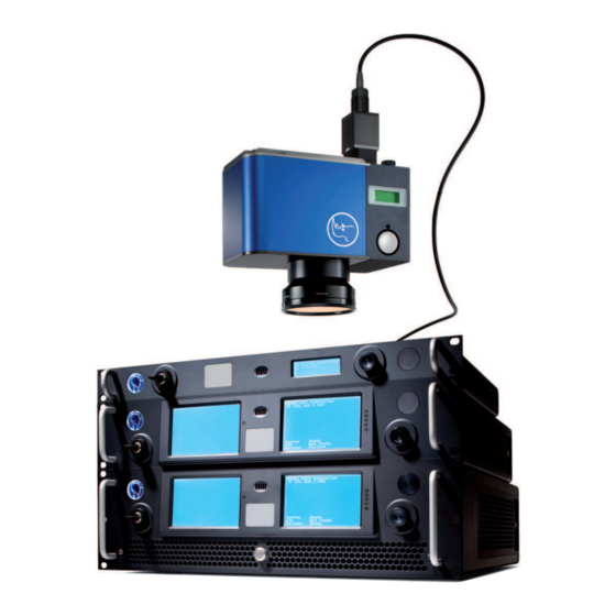
Figure 3.4: Location of the PWR and DC INPUT connector Step 3 Only ASC-3: Connect the ARGES System Controller’s fiber coupling with the scan head: ARGES System Controller · ASC-1, ASC-2 and ASC-3 · Operator_Manual.tex · 1.0 · accepted · 2009-05-08 · 11:55 · 42 (77) -
Page 43: Connect To Laser
The laser’s power supply provides a supply voltage of +24 V, 10 A. ARGES System Controller · ASC-1, ASC-2 and ASC-3 · Operator_Manual.tex · 1.0 · accepted · 2009-05-08 · 11:55 · 43 (77) -
Page 44: Connect To Peripheral Devices
Connect the ARGES System Controller via the connectors at its rear panel to the periph- erals. The connectors are described in section Identification of Interfaces on page 17. ARGES System Controller · ASC-1, ASC-2 and ASC-3 · Operator_Manual.tex · 1.0 · accepted · 2009-05-08 · 11:55 · 44 (77) -
Page 45: Configure Device Drivers
This section states measures to start regular operation; this comprises the preparation of the System, switching on the devices, loading the software, supplying with initial information, etc. ARGES System Controller · ASC-1, ASC-2 and ASC-3 · Operator_Manual.tex · 1.0 · accepted · 2009-05-08 · 11:55 · 45 (77) -
Page 46: Resuming Operation
• In InScript in the Devices List window the sas device’s Status indicates ready • At the ASC-3 the display indicates Devices ready ARGES System Controller · ASC-1, ASC-2 and ASC-3 · Operator_Manual.tex · 1.0 · accepted · 2009-05-08 · 11:55 · 46 (77) -
Page 47: Measures To Execute And Supervise Operations
This section states all characteristics describing an error situation or which point to a failure in the system. (Turn page, please) ARGES System Controller · ASC-1, ASC-2 and ASC-3 · Operator_Manual.tex · 1.0 · accepted · 2009-05-08 · 11:55 · 47 (77) -
Page 48: Leds At The Arges System Controller Front Panel
4 Measures to Execute and Supervise Operations Figure 4.1: LEDs at the ARGES System Controller front panel ARGES System Controller · ASC-1, ASC-2 and ASC-3 · Operator_Manual.tex · 1.0 · accepted · 2009-05-08 · 11:55 · 48 (77) - Page 49 (in development) – off (in development) green (in development) yellow (in development) – off (in development) yellow (in development) ARGES System Controller · ASC-1, ASC-2 and ASC-3 · Operator_Manual.tex · 1.0 · accepted · 2009-05-08 · 11:55 · 49 (77)
-
Page 50: Leds At The Arges System Controller Rear Panel
4 Measures to Execute and Supervise Operations Figure 4.2: LEDs at the ARGES System Controller rear panel ARGES System Controller · ASC-1, ASC-2 and ASC-3 · Operator_Manual.tex · 1.0 · accepted · 2009-05-08 · 11:55 · 50 (77) - Page 51 Gate and First Pulse Kill signal green (in development) First Pulse Kill signal Rem: with Monoflop 100 ms Continued on next page ARGES System Controller · ASC-1, ASC-2 and ASC-3 · Operator_Manual.tex · 1.0 · accepted · 2009-05-08 · 11:55 · 51 (77)
- Page 52 Ethernet OS state off operating system is shut down; device may be switched off Continued on next page ARGES System Controller · ASC-1, ASC-2 and ASC-3 · Operator_Manual.tex · 1.0 · accepted · 2009-05-08 · 11:55 · 52 (77)
- Page 53 (in development) power OK off (in development) not active or shut down due to emergency stop Continued on next page ARGES System Controller · ASC-1, ASC-2 and ASC-3 · Operator_Manual.tex · 1.0 · accepted · 2009-05-08 · 11:55 · 53 (77)
-
Page 54: Only Asc-3
• Failure at the connections to the LASER POWER BREAKER connector, Connect to Interlock and Laser Pilot Light on page 43. ARGES System Controller · ASC-1, ASC-2 and ASC-3 · Operator_Manual.tex · 1.0 · accepted · 2009-05-08 · 11:55 · 54 (77) -
Page 55: Preventing Errors
Step 4 Pull out the button and hold it. Step 5 Push the air filter cartridge back to its place. Step 6 Push in the button. ARGES System Controller · ASC-1, ASC-2 and ASC-3 · Operator_Manual.tex · 1.0 · accepted · 2009-05-08 · 11:55 · 55 (77) -
Page 56: Template: Logbook
Figure 4.3: Removing an air filter cartridge... - Page 57 4.2 Preventing Errors ARGES System Controller · ASC-1, ASC-2 and ASC-3 · Operator_Manual.tex · 1.0 · accepted · 2009-05-08 · 11:55 · 57 (77)
-
Page 58: Correcting Errors
This software package is initially installed by ARGES on each ASC controller. There is no need to download a module, unless you want to update it for concrete technical reason. ARGES System Controller · ASC-1, ASC-2 and ASC-3 · Operator_Manual.tex · 1.0 · accepted · 2009-05-08 · 11:55 · 58 (77) -
Page 59: Updating Procedure
ARG_ASC_SW in the tables on the page http://www.arges.de → Downloads → ASC Modules. Step 9 Download the module updates from the respective table. ARGES System Controller · ASC-1, ASC-2 and ASC-3 · Operator_Manual.tex · 1.0 · accepted · 2009-05-08 · 11:55 · 59 (77) -
Page 60: Reboot
If the action failed then terminate operation, see page 61. If even that fails then interrupt operation, see page 61. ARGES System Controller · ASC-1, ASC-2 and ASC-3 · Operator_Manual.tex · 1.0 · accepted · 2009-05-08 · 11:55 · 60 (77) -
Page 61: Measures To Interrupt Or Terminate Operation
Step 1 If instances of the InScript software are connected to the ARGES System Controller then exit these instances. ARGES System Controller · ASC-1, ASC-2 and ASC-3 · Operator_Manual.tex · 1.0 · accepted · 2009-05-08 · 11:55 · 61 (77) -
Page 62: Postprocessing
In the case where any postprocessing should be required after terminating the operation, this is stated here. There is no postprocessing necessary. ARGES System Controller · ASC-1, ASC-2 and ASC-3 · Operator_Manual.tex · 1.0 · accepted · 2009-05-08 · 11:55 · 62 (77) -
Page 63: Security Regulations
Check the laser device at least once per shift for signs of visible damage and also the safety equipment (e.g. defective safety glass or safety circuits). Immediately repair or eliminate faults that degrade safety. ARGES System Controller · ASC-1, ASC-2 and ASC-3 · Operator_Manual.tex · 1.0 · accepted · 2009-05-08 · 11:55 · 63 (77) - Page 64 Under these circumstances, take appropriate measures to protect personnel in this area from laser radiation (e.g. by using safety walls, suitable goggles and protective clothing). ARGES System Controller · ASC-1, ASC-2 and ASC-3 · Operator_Manual.tex · 1.0 · accepted · 2009-05-08 · 11:55 · 64 (77)
- Page 65 Use operating and alignment equipment specified in this document. Follow the procedures specified in this document. ARGES System Controller · ASC-1, ASC-2 and ASC-3 · Operator_Manual.tex · 1.0 · accepted · 2009-05-08 · 11:55 · 65 (77)
-
Page 66: Danger Notes
Avoid eye or skin exposure to direct or scattered radiation. Wear suitable protective goggles. The following are hazardous: • Direct radiation • Reflected radiation • Diffuse scattered radiation ARGES System Controller · ASC-1, ASC-2 and ASC-3 · Operator_Manual.tex · 1.0 · accepted · 2009-05-08 · 11:55 · 66 (77) - Page 67 ARGES System Controller · ASC-1, ASC-2 and ASC-3 · Operator_Manual.tex · 1.0 · accepted · 2009-05-08 · 11:55 · 67 (77)
- Page 68 The high output power from a class 4 laser can set on fire a wide range of materials Before opening the beam path appropriate fire prevention has to be taken. ARGES System Controller · ASC-1, ASC-2 and ASC-3 · Operator_Manual.tex · 1.0 · accepted · 2009-05-08 · 11:55 · 68 (77)
-
Page 69: High Voltage
These technicians have to be briefed about the dangers associated with laser radiation. Always observe the following 5 safety rules when working on electrical components: ARGES System Controller · ASC-1, ASC-2 and ASC-3 · Operator_Manual.tex · 1.0 · accepted · 2009-05-08 · 11:55 · 69 (77) -
Page 70: Noxious Gases And Vapors
Always follow all relevant safety regulations when carrying out any work on laser equipment. ARGES System Controller · ASC-1, ASC-2 and ASC-3 · Operator_Manual.tex · 1.0 · accepted · 2009-05-08 · 11:55 · 70 (77) - Page 71 Raised dust or fume must not be inhaled and must not get in contact with the human skin ARGES System Controller · ASC-1, ASC-2 and ASC-3 · Operator_Manual.tex · 1.0 · accepted · 2009-05-08 · 11:55 · 71 (77)
-
Page 72: Optics
Send the material back to the supplier or man- ufacturer of the optics. He is accountable and responsible for proper disposal of the material. ARGES System Controller · ASC-1, ASC-2 and ASC-3 · Operator_Manual.tex · 1.0 · accepted · 2009-05-08 · 11:55 · 72 (77) -
Page 73: Cooling Water
Dry the skin or mucous membranes very well with a clean cloth if they come into contact with cooling water. ARGES System Controller · ASC-1, ASC-2 and ASC-3 · Operator_Manual.tex · 1.0 · accepted · 2009-05-08 · 11:55 · 73 (77) -
Page 74: Liability
7.3 Risc Assessment (in development) ARGES System Controller · ASC-1, ASC-2 and ASC-3 · Operator_Manual.tex · 1.0 · accepted · 2009-05-08 · 11:55 · 74 (77) -
Page 75: Repair
8.2 Disposal of Product If you want disposal of the product then return it to ARGES for the following reasons, please. ARGES System Controller · ASC-1, ASC-2 and ASC-3 · Operator_Manual.tex · 1.0 · accepted · 2009-05-08 · 11:55 · 75 (77) - Page 76 Step 1 Decommission the product according to chapter Postprocessing on page 62. Step 2 Return the product according to section Return of Product on page 75. ARGES System Controller · ASC-1, ASC-2 and ASC-3 · Operator_Manual.tex · 1.0 · accepted · 2009-05-08 · 11:55 · 76 (77)
-
Page 77: Form: Return Delivery To Manufacturer
Return Delivery to Manufacturer Address: ARGES GmbH Werk 4 92442 WACKERSDORF ALLEMAGNE Phone: +49 9431 7984–0 Fax: +49 9431 7984–300 E-mail: info@arges.de Internet: http:/ /www.arges.de From: Company: Name: Phone: Country of origin: Germany Original product value: Original invoice number: RMA number:... -
Page 79: License Notices
Please send us your inquiry to: info@arges.de You will find the complete text of the GPL below. Further information about the GPL as well as official translations in various languages can be found at:... - Page 80 your freedom to share and change free software–to make sure the software is free for all its users. This General Public License applies to most of the Free Software Foundation’s software and to any other program whose authors commit to using it.
- Page 81 TERMS AND CONDITIONS FOR COPYING, DISTRIBUTION AND MODIFICATION 0. This License applies to any program or other work which contains a notice placed by the copyright holder saying it may be distributed under the terms of this General Public License. The ”Program”, below, refers to any such program or work, and a ”work based on the Program”...
- Page 82 c) If the modified program normally reads commands interactively when run, you must cause it, when started running for such interactive use in the most ordinary way, to print or display an announcement including an appropriate copyright notice and a notice that there is no warranty (or else, saying that you provide a warranty) and that users may redistribute the program under these conditions, and telling the user how to view a copy of this License.
- Page 83 c) Accompany it with the information you received as to the offer to distribute corresponding source code. (This alternative is allowed only for noncommer- cial distribution and only if you received the program in object code or exe- cutable form with such an offer, in accord with Subsection b above.) The source code for a work means the preferred form of the work for making mod- ifications to it.
- Page 84 7. If, as a consequence of a court judgment or allegation of patent infringement or for any other reason (not limited to patent issues), conditions are imposed on you (whether by court order, agreement or otherwise) that contradict the conditions of this License, they do not excuse you from the conditions of this License.
- Page 85 the option of following the terms and conditions either of that version or of any later version published by the Free Software Foundation. If the Program does not specify a version number of this License, you may choose any version ever published by the Free Software Foundation.
- Page 86 END OF TERMS AND CONDITIONS How to Apply These Terms to Your New Programs If you develop a new program, and you want it to be of the greatest possible use to the public, the best way to achieve this is to make it free software which everyone can redistribute and change under these terms.
- Page 87 The hypothetical commands ‘show w’ and ‘show c’ should show the appropriate parts of the General Public License. Of course, the commands you use may be called something other than ‘show w’ and ‘show c’; they could even be mouse-clicks or menu items–whatever suits your program.
Need help?
Do you have a question about the ASC-1 and is the answer not in the manual?
Questions and answers