Table of Contents
Advertisement
Quick Links
Instruction manual
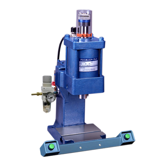
FCC Pneumatic Press
Model:FCP-100,200,500,750H,1000
Make sure to read this manual before using this press. Then,
store it in a safe location. The specifications may be changed
without prior notice.
for
(Ver.3.01)
FUJI CONTROLS CO., LTD.
1-5-6, Iidabashi, Chiyoda-ku, Tokyo 102-0072
Phone: 03-3265-5437
Fax: 03-3265-5430
April 04, 2013
Advertisement
Table of Contents

Summary of Contents for FUJI CONTROLS FCP-100
- Page 1 (Ver.3.01) Make sure to read this manual before using this press. Then, store it in a safe location. The specifications may be changed without prior notice. FUJI CONTROLS CO., LTD. 1-5-6, Iidabashi, Chiyoda-ku, Tokyo 102-0072 Phone: 03-3265-5437 Fax: 03-3265-5430 April 04, 2013...
- Page 2 Thank you very much for purchasing our pneumatic press. In order to get the most out of this product, make sure to read all of this manual before using the press. Store this manual carefully in order to refer it when necessary, and make full use of the press for a long time.
- Page 3 Unless otherwise specified, "raise" and "lower" means raising and lowering the press ram. ± Power source This press requires 100 VAC 10%, 50/60 Hz. CAUTION: Connecting a power supply that is different from this specification may cause a fire or result in bodily injury. Supplied air pressure The compressed air pressure used with this press should be 0.2 to 0.5 MPa.
- Page 4 When removing the hose CAUTION: Never touch the jig or metal die. When compressed from the air supply inlet air is not supplied, the press ram may fall and you may be crushed by the jig or metal die when removing the hose from the air supply inlet.
-
Page 5: Table Of Contents
TABLE OF CONTENTS page Name and function of each part on the Press - Model FCP Installation and preparation for operation 1. Installation Method 2. Preparation Adjustment of each section 1. Mold Matching (inching operation) 2. Stroke Adjustment Options Maintenance Spare parts Wiring diagram Diagrams of Air circuit... -
Page 6: Name And Function Of Each Part On The Press - Model Fcp
NAME FUNCTION ① Main solenoid valve An electrically operated solenoid valve, 100 VAC 50/60 Hz. ② Inching valve By closing this valve, the air exhaust path is blocked and the press ram will stop rising. Used for Mold matching operations. Normally this valve is left completely open. ③... - Page 7 ⑬ Column The column contains an integrated air tank. This tank keeps the press output constant, even if there is a fluctuation in the compressed air supplied. (This tank is not installed on the FCP-100 and FCP-200.) - 2 -...
-
Page 8: Installation And Preparation For Operation
1. Installation Method 1) The pneumatic press is delivered in a wooden crate. The bottom of the crate is a pallet and forklift forks can be inserted under it. The press housing is attached to the pallet using bolts and nuts. 2) Move the press to the installation position as though it were a wooden crate, using a forklift or a similar transportation device. -
Page 9: Stroke Adjustment
2. Stroke Adjustment Adjust the lower stroke of the press ram by adjusting the mechanical stopper. First loosen the cap screw on the upper section of the stopper. The stopper itself is threaded and will turn. (Turn the stopper clockwise to shorten the press ram stroke.) After adjusting the stopper position, tighten the cap screw again. -
Page 10: Maintenance
Contact telephone for user support (Engineering division): 81-3-3265-5437 (only in Japanese) Or, ask questions by e-mail please. E-mail:sales@fujicon.net Please make sure to check the model name and serial number before calling. Model No, Suppliers Parts FCP-100 FCP-200 FCP-500 FCP-750H FCP-1000 ① Quick Exhaust Valve AQ400-03 ②... -
Page 11: Wiring Diagram
Solenoid Valve Two-handed Pushbutton Switches Plug FCP-100 F i l t e r & R e g u l a t r S o l e n o i d V a l v e S i l e n c e r... - Page 12 FCP-750H S i l e n c e r I n c h i n g V a l v e F i l t e r & R e g u l a t r S i l e n c e r S p e e d C o n t r o l l e r Q u i c k E x h a u s t V a l v e A i r O u t l e t A i r t a n k...
-
Page 13: Specifications
1. Dimensional Specifications T-s lot Base pla te of mod el FCP Model FCP-100 FCP-200 FCP-500 FCP-750H FCP-1000 Dimensions (mm ) ( mm ) (mm ) (mm ) 4- φ 10 4- φ 10 4- φ 12 4- φ 12 4-φ... -
Page 14: Apparent Power Of Solenoid Valve (Unit:va)
2. Apparent Power of Solenoid Valve (unit:VA) FCP-100 FCP-200 FCP-500 FCP-750H FCP-1000 In-rush Holding 3. Air Consumption (unit:NI) FCP-100 FCP-200 FCP-500 FCP-750H FCP-1000 - 9 -... -
Page 15: Press Output Chart
F CP -1 0 0 F CP -2 0 0 F CP -2 0 0 Press output Press output 3 . 0 k N 1 . 5 k N 1. 1 2 1. 9 6 2 . 0 k N 1...
Need help?
Do you have a question about the FCP-100 and is the answer not in the manual?
Questions and answers