Advertisement
Quick Links
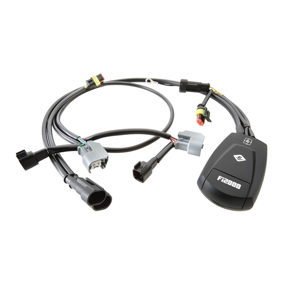
Items Supplied >
1 – Fi2000CL Fuel Injection Module
4 – Zip Ties 6"
1 – Zip Tie 4"
1 – Velcro Stripe
Instruction Manual >
Read all instructions carefully and completely before installing your new Fi2000CL module. It is
recommended that a qualified mechanic or technician install this product.
Remove the seat, and air cleaner assembly, remove both front and rear gas tank mounting bolts. Prop the
1.
rear of the gas tank up approximately 2"-4" with a small block.
Remove left side cover by pressing plastic tab upward and pulling bottom of steel cover outward and up to
2.
release from upper retaining tabs, see Figure 1.
Pull engine ECU outward by releasing from retaining tab to allow for Fi2000 wire harness installation, Figure 2.
3.
Pull existing wire harnesses out from under the seat frame area. Place the Fi2000 tuner and harness in the
4.
area which is under the seat, see Figure 3. Route the two longer Fi2000 harnesses through the left side
cover area where the ECU was pulled out, see Figure 2, and continue routing both through the hole at the
front of the left side cover inner housing, be sure to REVIEW in Figure 2! The longest harness must be
routed to the right side of the motorcycle next to the starter, and ground lug on case. The other harness will
go to the injectors. Once harnesses have been pulled into place, be sure to reinstall engine ECU back into
place, being sure none of the harnesses get stuck on the other electrical components, it must snap back into
place under the tab.
Route the injector harness to the front and rear fuel injectors located between the cylinder heads, along the
5.
right side of the upper frame backbone. Place the harness in the plastic harness channel provided along
the frame. Locate the factory connector on each fuel injector. Depress the clip on the connector and pull the
connector free and move it out of the way. Note: A pair of needle nose pliers and a long flat blade
screwdriver helps with this job. Attach the pair of Fi2000 module's injector connectors labeled "FRONT" to
the front injector. Take the original HD connector and insert the corresponding Fi2000 connector into it, refer
to Figure 4.
Attach the Fi2000 module's remaining injector connectors labeled "REAR" onto the rear injector. Then take
6.
the original HD connector and insert the corresponding Fi2000 connector into it, refer to Figure 4. Secure
the Fi2000 injector harness to one of the existing HD harnesses, at the front of the plastic harness tray,
along the frame rail, under the tank, using the supplied 4" zip tie.
Remove right side cover by removing Phillips screw at bottom of cover and lifting bottom of cover outward
7.
and up to release from upper tabs. Route the black ground wire from the Fi2000 through the gap just under
the frame and to the rear of the battery box. Attach the ring terminal to the negative post of the battery.
8. Route the longest Fi2000 oxygen sensor harness from rear of engine area to below battery and next to
starter. Remove the nut securing ground wire and pull off ground wire to allow connectors to pass through
between rear of transmission case and harness sheath in front of swingarm, see Figure 5. Reinstall nut
securely!
DISCLAIMER: NOT LEGAL FOR SALE OR USE IN CALIFORNIA ON ANY POLLUTION CONTROLLED
.
MOTOR VEHICLES
DOCUMENT NO. 0017
REV. A
04/17
23801 E. La Palma Ave., Yorba Linda, Ca 92887 Ph. 714.692.8180, Fax. 714.692.5016
®
Application(s) >
HARLEY DYNA
692-1616CL
1
www.cobrausa.com
2012-2017
Page 1 of 4
Advertisement

Related Manuals for Cobra USA Fi2000

Summary of Contents for Cobra USA Fi2000
- Page 1 Remove right side cover by removing Phillips screw at bottom of cover and lifting bottom of cover outward and up to release from upper tabs. Route the black ground wire from the Fi2000 through the gap just under the frame and to the rear of the battery box. Attach the ring terminal to the negative post of the battery.
- Page 2 13. Remove the backing from the Velcro and attach the Velcro pad down between the back of the battery and the ECU on the flat area of the frame. Apply the mating Velcro to the back of the Fi2000 and attach, see Figure 3.
- Page 3 With the red pot turned to its maximum (10) position, the Fi2000 will cope with nearly 100 R.W. horsepower. You can generally, if you are using quality performance engine upgrades, in a sensible combination equate the numbers evenly from 2 up to 10 based on horsepower gains.
- Page 4 PLASTIC PANEL, MATING CONNECTOR SECURED NEXT TO IT. VOLTAGE REGULATOR BOLTS REMOVED AND REGULATOR LOWERED FOR ACCESS TO O CONNECTORS REMOVE GROUND NUT FOR FRONT Fi2000 O HARNESS FIGURE 5 FIGURE 6 INSTALLATION Stock w/ Slip-on Mufflers Default Pot Settings: Green Yellow...
Need help?
Do you have a question about the Fi2000 and is the answer not in the manual?
Questions and answers