Advertisement
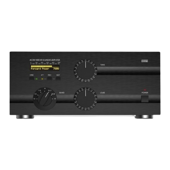
ACOM1000 TUBE REPLACEMENT INSTRUCTION
-------------------------------------
This step-by-step instruction is about the tube replacement and idling currents re-adjustment of
ACOM1000 power amplifier. Please follow all details closely since the work is difficult, with many
details to keep track about, and might be dangerous too. Do not hesitate to contact your local
dealer or nearest ACOM's service for any advice. Please don't attempt tube replacement by
yourself, if you don't feel comfortable with repairs!
W A R N I N G HIGH VOLTAGE!
=========================
The amplifier works with high voltages up to 3000V which is LETHAL! For your safety pull the
amplifier power plug out of the mains wall outlet and WAIT AT LEAST 30 minutes EACH TIME
BEFORE you remove the cover of the amplifier. Disconnect all cables from the amplifier (grounding
last). Do not touch any part inside before ensuring as described below that no residual voltages
are present!
1. REMOVING THE TOP COVER.
a) First pull the amplifier power plug out of the mains wall outlet. Wait at least 30 minutes (or
more if the amplifier has been just powered up).
b) Using a Philips-2 screwdriver, unscrew 9 pcs of "eco-fix" flange-button head screws to release
the top cover (2x3 pcs on each bottom-side edge, and three more on the rear-top edge of the
box). Don't unscrew four screws that hold the grid above the tube. Keep all screws and washer for
the mounting procedure later.
Lift the rear edge of the cover slightly (to 2-3cm) and then pull the cover backwards, in order to
release it from front-panel's chutes. Remove the top cover. Do not touch the part inside for now!
You will see inside:
- the MAINS PCB that is mounted on an aluminum sub-chassis, just above the big HV transformer;
- the HV rectifier PCB in front of the MAINS PCB (with four big diodes, one wire-wound resistor,
and one disc ceramic capacitor on it);
- the HV filter PCB, located just below the HV rectifier (with 8 electrolytic capacitors on it).
c) Before proceeding, please make sure that no residual DANGEROUS VOLTAGES are present in the
amplifier. For this purpose take approximately 1m of WELL-INSULATED lead (adequate for 3000V).
Bare it to about 1cm at both ends.
Tighten one end of the wire under the GROUND STUD (on the rear panel). Only AFTERWARDS,
holding the wire BY THE INSULATION, at a distance of minimum 10cm (4 Inch), touch with its
second end consecutively all parts on the HV rectifier PCB, especially:
- the HV output J3;
- the wire-wound resistor R12 on its both sides;
Advertisement
Table of Contents

Summary of Contents for Cubicom ACOM1000
- Page 1 This step-by-step instruction is about the tube replacement and idling currents re-adjustment of ACOM1000 power amplifier. Please follow all details closely since the work is difficult, with many details to keep track about, and might be dangerous too. Do not hesitate to contact your local dealer or nearest ACOM's service for any advice.
- Page 2 - the four HV diodes on their both sides. With the same wire end, on the MAINS PCB touch the diode D19 on its both sides (it is located at the PCB edge, near the powerful transistor that is installed on the chassis). 2.
- Page 3 Examine new tube pins before inserting it in the socket. They must be straight and not inclined in respect to the ceramic base, otherwise any bent pin could damage the socket's spring contacts, and thus the socket and/or the tube may become unusable. a) Put carefully the new tube ON the socket, without neither pressing nor inserting the pins.
- Page 4 plate current during this adjustment. The adjustment trimmer-potentiometers is located on the MAINS PCB. a) Install the cover above the RF deck (15 countersunk screws). In two of the nuts on the middle chassis panel, near the HV LID crowbar and the cover-presence micro-switch sensor, tighten two small strip pieces in order to imitate top cover.
- Page 5 At last, install the top cover again as described below. Be careful to align screws thread to the nuts and do not force them since any captive nut on the chassis might be damaged. a) Put the cover above the chassis, while holding its rear edge slightly lifted (to 2-3cm). Align its horizontal and two vertical front edges to the respective front-panel chutes.
Need help?
Do you have a question about the ACOM1000 and is the answer not in the manual?
Questions and answers