Advertisement
Quick Links
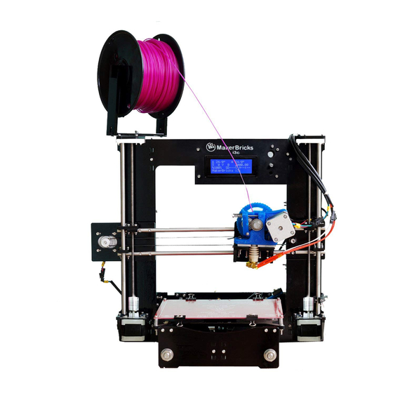
I3c 3d printer
------User manual ------
MakerBricks i3c 3D Printer
Dear Maker,
Thank you for purchasing the MakerBricks i3c 3D Printer kit.
Your kit contains a set of pre-assembled components. This manual has
all the instructions to assemble them into a 3D printer. You will also
find instructions to operate the 3D printer
.
If you have any questions feel free to e-mail us at:
support@makerbricks.com
Thanks,
MakerBricks Team
Advertisement

Summary of Contents for MakerBricks I3c
- Page 1 MakerBricks i3c 3D Printer Dear Maker, Thank you for purchasing the MakerBricks i3c 3D Printer kit. Your kit contains a set of pre-assembled components. This manual has all the instructions to assemble them into a 3D printer. You will also...
- Page 2 P a g e support@makerbricks.com Table of content: Safety precautions 2. List of sub-assemblies 3. Assembling the printer Z-axis assembly Y-axis assembly X-axis assembly Top mount assembly Extruder & Hotend assembly Spool holder assembly 4. Wiring the printer 5. Setup before printing 6.
- Page 3 P a g e List of sub-assemblies: X-AXIS Y-AXIS MAIN FRAME SIDE PLATES...
- Page 4 P a g e ASSEMBLING SIDE PLATES TO THE MAKERBRICKS MAIN FRAME On the back side of the main frame there are six L- brackets. Two brackets fixed on top are for mounting the top mount plate to the main frame.
- Page 5 P a g e Y-AXIS ASSEMBLY: Cut the zip ties on both the corners of the bed plate There are two slots on the mainframe for fixing Y-axis. Slide the y-axis assembly into the main frame Make sure the motor on the Y-axis should be inside the frame.
- Page 6 P a g e X-AXIS ASSEMBLY: Pass the X-axis assembly into the threaded rods on the main frame. Now insert the smooth rods into the bearings on both sides of the X-axis assembly. Smooth rods should be fixed in the acrylic part on the Z-axis motor mount plates.
- Page 7 P a g e TOP MOUNT PLATE ASSEMBLY: Top mount plate should be fixed to the mainframe by passing 2 m3 screws through the top mount plate into the L-brackets marked in red in below picture. Place the top mount plate on the frame as shown below.
- Page 8 P a g e SPOOL HOLDER ASSEMBLY: Take the following acrylic parts and M3x16mm screws and M3 Nuts. Fix the side plate with the POWER SUPPLY to the left side of the mainframe. Place the side plate in such a way that the L-Brackets should Face outside.
- Page 9 P a g e AFTER ASSEMBLY Do the same for fixing another part. AFTER...
- Page 10 P a g e...
- Page 11 P a g e | 10 WIRING: X- axis motor ----> connect the wire with XM label to X- motor...
- Page 12 P a g e | 11 Y- axis motor ----> connect the wire with YM label to Y- motor Z- axis motors ----> connect the wire with ZM label to Z- motor Extruder motor ----> connect wire with EM label to extruder motor X-axis limit switch/End stop.
- Page 13 P a g e | 12 Zip tie the Y-Motor wire, Y-limit switch wire, X-Motor wire, Z-Motor wire, X-limit switch wire all together inside the printer. Top view Pass all the wires mentioned above through the hole at the bottom of the right side plate.
- Page 14 P a g e | 13 Zip tie the extruder motor wire, Hot end wires & fan wire all together. Zip tie the above mentioned wires to the holes on the right side of the top mount plate. ...
- Page 15 P a g e | 14 RAMPS BOARD SCHEMA Note: The actual board colour may vary from the board shown in pictures LIMIT SWITCH (END STOPS) WIRING Connect the limit switch wires to the board as shown above The red wire should be on left and the black wire should be on right side NOTE: if the limit switch wires are connected wrong then no power will pass through the board.
Need help?
Do you have a question about the I3c and is the answer not in the manual?
Questions and answers