Table of Contents
Advertisement
Quick Links
Advertisement
Table of Contents

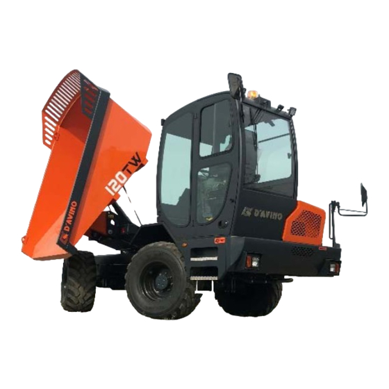
Summary of Contents for AMOG D'AVINO 120TW
- Page 1 120TW Manuale di Uso User Manual DUMPER Manuel d’Utilisation Manual de Uso Ed. 04 / Rel. 04 AMOG srl – Via Padula n.229/231 – 80031 Brusciano (NA) Italia – P.IVA 05818590639 Tel. 081 6588361 – Fax 081 8863398 – e‐mail: aftersales@davinogroup.biz – http://www.davinomixer.com...
- Page 2 - Pag. 1 DAVINO 120TW - USER AND MAINTENANCE MANUAL Rev.04...
- Page 3 It is important to read this manual thoroughly and thoroughly understand it well before starting any type of operation and/or intervention on the machine. The machine must only be used and operated by previously instruced personnl on the vehicle and its safety regulations, as well as be allowed to operate with the machine itself.
-
Page 4: Table Of Contents
INDEX INTRODUCTION………………………………………………………………………………………..…..……..Chapter 1 GENERAL INFORMATION………………….………………….……………………….….…….. SYNOPTIC TABLE.……………………………………………..………….………..……...……... DIRECTION REFERENCE…………..………………………….…………….……..….……..…. IDENTIFICATION OF THE MACHINE.………………...…….…………………… ..….……….. MANUFACTURER…………………………………...………………………………..………...…. TECHNICAL SUPPORT REQUEST……………………………………………………………... Chapter 2 TECHNICAL FEATURES……..……………………………………………………………..……. TECHNICAL PRESENTATION OF THE MACHINE...……..……………………………..……. FIGURE……………………………………………………………...………………………...……. REGULATIONS…………………………………………………………………………………..…. CONFORMITY CERTIFICATE CE…..……………………………………………………………. Chapter 3 SAFETY PRECAUTIONS...…………….………...……………………………..………………… PRECAUTIONS FOR USE…………………………………………………………………..…….. PRECAUTIONS AGAINST RESIDUAL RISKS..…………………………………………..……. - Page 5 ………………………………………………………. LATERAL MIRRORS ADJUSTMENT DRIVING SEAT ROTATION……………………………………………………………………..… START UP ENGINE…………………………………………………………………….………….. WHEEL ALIGNMENT…………………………..…………………………………………………... 6.10 STARTING AND DRIVING THE MACHINE………………………………………..……………. STOP OF THE MACHINE………………………………………………………………………….. 6.11 STOP OF THE ENGINE……………………………………………………………………………. 6.12 MACHINE PARKING……………………………………………………………………………….. 6.13 USE OF THE MACHINE DOWNHILL……………………………………………..……………… 6.14 LOAD AND UNLOAD OF DUMP…………………………………………………….……………. 6.15 TRANSPORTING THE MACHINE ON TROLLEY…………………………………….………...
-
Page 6: Introduction
This machine must only be used by the driver and is not intended for the carriage of other persons. No modification must be made to the machine without the permission of the AMOG, as the modification can lead to dangers. - Page 7 Use of the machine to perform operations other than those described is strictly forbidden. Any liability of the AMOG for any other use or failure to comly with the instructins give by the manufacturer is excluded. It is forbidden to carry objects of any nature inside the dump or the cabin.
- Page 8 AMOG assumes no responsibility for damages caused to persons, animals, porperty or environment resulting from the use of the machine by operators who do not meet the required requirements.
-
Page 9: Chapter 1 General Information
Chapter 1 – GENERAL INFORMATION SYNOPTIC TABLE Please take time to carefully read the following legend and familiarize yourself with the basic terminology and characteristics of the machine Frame Front Axle Rear Axle Right front mudguard Oil tank Cabin - Pag. 8 DAVINO 120TW - USER AND MAINTENANCE MANUAL Rev.04... - Page 10 Dump Engine hood Engine 10. Battery compartment 11. Left front mudguard 12. Fuel tank 13. Swivel Frame - Pag. 9 DAVINO 120TW - USER AND MAINTENANCE MANUAL Rev.04...
-
Page 11: Direction Reference
DIRECTION REFERENCE The orientation of the driving seat determines the direction of the machine. In Fig. 1 is represented the direction of advancement in TRANSFER condition (driving position facing the front of the machine), for more or less long journeys, with or without the transport of material. In Fig. -
Page 12: Identification Of The Machine
If the fault could not be found or resolved using the aforementioned methods DO NOT ATTEMPT to repair it. Such attempts may cause injury to you and or damage the machine. Contact the nearest AMOG Assistance Center or contact us directly at: Apart from the specifics of the fault in question, remember to have all identifying data on the machine on hand to assist us quickly in resolving the difficulty. -
Page 13: Chapter 2 Technical Features
Chapter 2 – TECHNICAL FEATURES TECHNICAL PRESENTATION OF THE MACHINE DESCRIPTION (ISO 7132:2003) Trilateral rear dumping dumper – Rigid frame – N. 2 axles - N.4 wheels steering/drive – Rotating driving seat – Max load capacity 12.000 kg ENGINE Manufacturer Perkins 904J-E36TA Model... - Page 14 TRANSMISSION Integral 4x4 N. speed front/rear 4 (2 mechanical + 2 hydraulic) Max speed 35 km/h Max slope Hydrostatic Transmission: “Automotive” formed by a variable displacement pump and variable motor by - Electro-hydraulic Control for hydraulic speed selection “slow” / “fast” speed and reverse Two-speed mechanical Reducer with electro-hydraulic control for "work"...
- Page 15 ELECTRICAL SYSTEM Voltage 12 V Battery 50 Ah (1000A) TIRES 500/60 R22,5 – TWIN RADIAL Front and rear Inflation pressure 4,0 bar DIMENSIONS Maximum Lenght 5.325 mm Maximum Width 2.550 mm Maximum Height (transfer mode) 3.130 mm Ground clearance 370 mm Maximum angle 24°...
-
Page 16: Figure
FIGURE - Pag. 15 DAVINO 120TW - USER AND MAINTENANCE MANUAL Rev.04... -
Page 17: Regulations
European Directive 2000/14 Acoustic emission ENGINE EU STAGE V / EPA Tier 4 ROPS ISO 3471 FOPS LEVEL II ISO 3449 STANDARD QUALITY AMOG srl is a certified company: ISO 9001 - 2015 - Pag. 16 DAVINO 120TW - USER AND MAINTENANCE MANUAL Rev.04... -
Page 18: Conformity Certificate Ce
2.4 CONFORMITY CERTIFICATE CE The machine is accompanied by a CE mark in accordance with the "essential health and safety requirements" provided for by the Machinery Directive of the European Union, 2006/42 / EC. Anyone who make a change that compromises the safety of the machine is responsible for the consequences that may result from it The CE declaration of conformity is the document signed by the manufacturer that guarantees and certifies that the machine complies with the European regulatory provisions regarding the product. -
Page 19: Chapter 3 Safety Precautions
PRECAUTIONS FOR ACCESSORIES When installing optional components or equipment, security issues maya rise. So always ask for advice from AMOG srl. The company does not respond to injury, accidents or malfunctions resulting from the use of unauthorized equipment or accessories. - Page 20 TRANSLATION OF PERSON OR PURCHASES The machine is not approved for the transportation of other persons besides the operator who must be in the driving position of the machine. Do not leave people outside the machine during work. Do no allow anyone to get on the work equipment. Do not carry persons on board the machine.
- Page 21 If the structure was involved in an accident, do not use the machien until the facility has been replaced or inspected by qualified personnel. The ROPS structure guarantees a safe guard if the operator has properly secured the seat belt. For this reason always keep the seat belt secure while the machine is in operation.
- Page 22 PRECAUTIONS DURING TRANSFER Before moving the car, check that there are no people nearby. Use the horn and follow signs and flags. Always keep a clear view of the entire work area or maneuver. If windows are installed in the cabin, they must always be clean and intact.
- Page 23 In places where there are underground water and gas pipes or high voltage cable pipes, contact the public service to identify the location. Make sure these structures are not damaged. Take special precautions when working near ditches, scuba diving or close to open exacations. To carry out water operations or cross sand banks, check the condition of the stand and the depth and speed of thee water flow.
- Page 24 PRECAUTIONS DURING WORKING OPERATIONS Do not take alcohol, drugs, or other substances that may affect your ability to work with operating machines before or during work. In case of extreme fatigue or malaise, do not use the machine; always pay close attention at the beginning and end of the shift.
- Page 25 When working on a slope and the fuel tank warning light comes on, immediately refuel, due to the inclination under the machine, the engine can suck air and stop suddenly, seriously jeopardizing the safety of the operator and people downstream of the vehicle. The gradient degree should be assessed depending on the following facors, such as terrain type, load, vehicle conditions, speed and visibility.
- Page 26 MACHINE PARKING Chosse a parking zone where other vehicles do not operate. Park the machine on a stable ground and possibly flat. Do not park the car at the end of the day or working day in the streams or river basins. Never park in the descent without first locking the machine to prevent accidental movement by means of external means.
-
Page 27: Precautions Against Residual Risks
PRECAUTIONS AGAINST RESIDUAL RISKS SLIPPING The guide station, the steps and the handlebars must always be clean and free from any foreign objects or traces of grease, oil, mud or water in order to reduce the risk of slipping. Pay attention to possible slippage of the stairs, as well as the ground around the machine. Always clean your shoes before climbing to avoid slipping or tripping. - Page 28 TIPPING The operator must know the performance, weight and maximum load transportable from the machine to ground conditions (flat, compact, sour, sloping). Always make sure that the car’s support area is sufficiently firm and sturdy to support its weight and therefore maintain adequate safety distance from the excavation edge.
- Page 29 The tire pressure values and the speed allowed in this manual correspond to the values provided by the manufactuer. For details, refer to the AMOG or tire manufactuer. DANGER OF ELECTRICAL NATURE Any type of intervention on the electrical system or the battery must be carried out by competent personnel.
- Page 30 FLUIDS HOT AND UNDER PRESSURE The hydraulic system is under pressure when the engine is running and can maintain the pressure even after it is switched off. Hot hydraulic oil causes severe burns. Wait for the oil to cool down before disconnecting the pipes. Pressure fluid leaks can be invisible. Do not use hands to check for leaks.
- Page 31 Check that there are no loose or damaged parts in the system. Tighten loose connetors or wiring terminals. If corroded and/or damaged cables or connections are made, immediately contact the zone dealer AMOG. Any type of intervention on the electrical system or the battery must be carried out by competent personnel.
-
Page 32: Precautions In Maintenance
PRECAUTIONS IN MAINTENANCE CORRECT MAINTENANCE Always follow the instructins given before using the machine or any other work on the machine. Please read all the provisions contained in this manual carefully. Always read the nameplates and instructions on the machine and the manual before starting any work on the machine. - Page 33 For lifting and transporting heavy parts, use cranes or hoists of adquate reach. Imburize the material in the best way. To use golfers if provided. Always make sure there are no people nearby. By disassembling or installin machine groups that must be supported by hydraulic or pneumatic lifting devices, it is advisable to ensure that the equipment of this equipment is appropriate for the load to be supported or moed.
- Page 34 When replacing a wheel, you must move the travel selector to neutral, turn off the engine and disengage the ignition key. This must be done on a flat and stable surface. Place a wedge under wheel diametrically opposite to the one you have to replace. Always place machine lifting equipment on a flat surface.
- Page 35 Do not operate the machine until the fault has been eliminated. No modification must be made to the machine without the authorization of AMOG because the modification can lead to dangers. .
-
Page 36: Stickers
Always keep decals readable; I no more readily avaialbe order a series at the AMOG parts service. Stickers should always be kept clean. For their cleaning, use detergent and water. - Page 37 DANGER – Do not climb the machine for inspection or to carry it; it is easy to slip and fall DANGER – if you overturn, do no laeve the driving seat, but cling firmly to the steering wheel Ma chine equipped with ROPS type protection DANGER –...
- Page 38 WARNING DECALS WARNING – This symbol indicates a diesel fuel tank, for filling instructinos consult the manual. DIESEL Fuel WARNING – This symbol indicates a hydraulic oil reservoir, for filling instructions consult the manual and the liquids table. . IDRAULICO Hydraulic Hydraulique WARNING - This symbol indicates the location of the Operator and Maintenance manual;...
-
Page 39: Safety Devices
SAFETY DEVICES The machine is equipped with a series of devices designed to protect the opeator, avoid unintentional drives and more generally use the machine safety. ROPS/FOPS PROTECTION STRUCTURE The cockpit is a ROPS/FOPS structure for the operator with a safety belt fastened against overturning and falling objects from above. - Page 40 MECHANICAL BLOCK ROTATION DRIVER’SEAT Block The guide post in the transfer or work configuration. To rotate the guide seat from the transfer configuration to the working one or vice versa, unhook the lock and rotate. After a rotation, make sure that the driving seat turns to the limit position and that the lock engages.
- Page 41 FLASHING LIGHT Visually Report the machine's progress. To Be used mandatory during the phases of road transfer, recommended during the working phases Mirrors Rear-view mirrors are important for the safe operation of the machine. It is of fundamental importance that they are properly regulated and intact.
- Page 42 MONITOR Inside the cabin, front and rear, there are n.2 monitors that allow the operator the visibility of the side of the machine behind him, whatever the position of the driver's seat (transfer or work) PLUG LOCK FOR DUMP ROTATION When inserted does not allow the rotation of the trailer.
- Page 43 DUMP FALL LOCK When The dump is lifted, inserting the plug into the special hole mechanically locks the accidental descent of the dump. Always Insert the retainer to carry out maintenance operations requiring the lifting of the dump. When not in use, the plug can be placed in the tubular pin holder inside the swivel frame. CABLES FOR END OF TRAVEL Present on both sides of the dump, ensure the mechanical end of the dump during the lifting phase...
- Page 44 FRONT AXLE LOCKING CYLINDER Intervenes by blocking the oscillation of the front axle, to assure the machine a higher stability when the dump is not positioned in the axle with the machine. To Restore the swing of the front axle, simply return the swivel frame to a locked position.
- Page 45 BATTERY SWITCH Located inside the battery compartment, it allows to disconnect the electrical system of the machine. Prevents accidental ignition of the machine, e.g. During maintenance, it avoids the battery discharge when the machine needs to remain stationary for a long time and allows to work safely on the electric circuit.
-
Page 46: Chapter 4 Preliminary Instructions And Running-In
Maintenance Timelines RUNNING IN Every AMOG machine is field-tested using all it’s components prior to shipping. Therefore, upon arrival, the required “Breaking In” period is 50 hours of operational use. During the “Breaking In” period operate with light to medium loads and at reduced speeds. This will allow the oil and hydraulic systems to reach normal operating temperature evenly. -
Page 47: Chapter 5 Instruments And Checks
Chapter 5 – INSTRUMENTS AND CHECKS The Operator’s skill and judgment impacts on the safety for himself/herself and others in the vicinity of the machine. It is imperative that the Operator knows the position and function of all machine controls. Every machine has it’s limitations: before operation, familiarize yourself with it’s abilities, characteristics, velocity, braking, steering, stability and load capabilities. -
Page 48: Driver's Position
DRIVER’S POSITION STEERING WHEEL It has a dual function: -Allow the change of direction of the machine -Rotate the guide seat – switch functions paragraph CABIN INSTRUMENTATION – BUTTON 2 In both cases, turn the steering wheel in the desired direction. Both with the driving position in the transfer and working condition, the steering direction corresponds to the operator's guide in that specific configuration. - Page 49 LEFT STEERING SELECTOR Allows to select hydraulic gears (slow and fast) and forward direction. Selection of hydraulic speeds Rotate the lever clockwise to select SLOW gear Rotate the lever counterclockwise to select FAST gear THE SELECTION FOR THE SLOW AND FAST GUIDE CAN BE CARRIED OUT ALSO TO MACHINE IN MOVEMENT.
- Page 50 ACCELERATOR PEDAL The pedal controls the engine speed and uses the automotive system to control the speed of the driven machine. With the pedal released the machine slows down until it stops. SERVICE BRAKE PEDAL The pedal drives multiple disc brakes. In the oil bath, with dual-circuit hydraulic transmission, acting on the wheels of both axles.
-
Page 51: Dashboard
DASHBOARD Includes: Matrix display 128x64 (protection degree IP66) nr.2 analog indicators : one for the cooling liquid engine temperature (right) and other one for the fuel level (left). n.19 alarms/signal pilot indicators; n.7 external switches to access to display functions. DISPLAY Following measures can be visues : Gears... - Page 52 b) Hydraulic gears There are two hydraulic gears: 1 - slow gear 2 - fast gear Hourcounter At the bottom, the total hour counter and the hourglass icon are displayed. The countdown counts the machine’s working hours (the count is only active when then engine ir running). The hourglass flashes once per second when the countdown counter is counting.
- Page 53 PILOT LIGHT Pilot Description Colour Description Alternator It lights when turn on the contact key, bifore to start the machine. Once the engine is on, it switches off to signal the good function of the machine. Candles It lights to signal the preheating fo the candles Amber when the starter switch and stop of the engine is on position 2.
- Page 54 High Exhaust System Temperature Indicates that a regeneration is underway Amber and that emission system temps are elevated Pressione Olio Trasmissione Lights up signalling the lack of oil pressure in the hydrostatic transmission Diesel Particulate Filter To indicate that the DPF is in need of Amber regeneration DPF Disabled Lamp...
- Page 55 Comes on when the fuel falls below the Fuel Reserve Amber reserve level Max Temperature Position lights illuminates when the coolant Water-Engine temperature of the engine exceeds 110 °c. Emission System Malfunction It turns on signaling a malfunction condition of the exhaust system.. Riserva DEF It lights up when the DEF drops below the reserve level.
- Page 56 KEYS 1 - Service button It allows you to access the service menu and view any engine error codes (see parag.13.13 – SERVICE and parag.13.12 – ENGINE) 2 – Driving Direction Selection Mode Key Allows to choose how you want to select direction of travel (see parag.5.2.1 – DRIVING DIRECTION SELECTION MODE) 3 –...
-
Page 57: Driving Direction Selection Mode Key
5.2.1 DRIVING DIRECTION SELECTION MODE KEY The button allows you to choose the mode of selection of the direction of travel Manipulator Left Steering Column(Devioguide)) (see parag.5.1 – DRIVER’SEAT) 1 – Right Manipulator Handle button (see parag.5.4 – MANIPULATOR) - Pag. 56 DAVINO 120TW - USER AND MAINTENANCE MANUAL Rev.04... -
Page 58: Key Selection Steering Mode
5.2.2 KEY SELECTION STEERING MODE The key is located on the dashboard and allows to select the 3 modes of steering: 1 – CRAB MODE (parallel drive): 4 steering wheels with the same steering angle, for a precise and safe approach to the loading/unloading points. 2 - 2 WD: 2 steer front wheels, for road transfer. -
Page 59: Mechanical Gear Shift Key
5.2.4 MECHANICAL GEAR SHIFT KEY The key selects the two mechanical gears Turtle: Working speed (1st mechanical gear) Hare: Transfer speed (2nd mechanical gear) During the phases of work and off-road movement it is recommended to use 1st mechanical gear. During the phases of movement on the road it is recommended to use the 2nd gear mechanical gear. -
Page 60: Cabin Insruments
CABIN INSTRUMENTATION ATTIC CONTROLS PANEL The attic control panel includes: A – Cabin ceiling light with pressure control B1 – Front wiper control button (2 speeds) B2 – Rear wiper control button (2 speeds) B3 – Front work headlights control keys (optional) C1 –... - Page 61 Air Conditioning Operation To obtain cold air in the cabin, proceed as follows: 1) Activate the knob D and select the desired fan speed (3 speeds) 2) Bring the knob to the OFF position And 3) Adjust the cooling intensity by adjusting the knob F 4) Orient as desired the nozzles G To obtain hot air in the cabin, proceed as follows: 1) Activate the knob D and select the desired fan speed (3 speeds)
- Page 62 SIDE CONTROL PANEL KEY 1 – FRONT AXLE LOCKING CYLINDER CONTROL Allows you to manually unlock the locking cylinder of the front axle and restore the swing of the axle when the body is not in axis with the machine. The locking cylinder of the front axle automatically intervenes when the body is positioned across the machine's axis, blocking the swing of the front axle to ensure greater stability.
-
Page 63: Joy Stick
JOY STICK CHASSIS SWIVEL CONTROL-X-X AXIS The movement along the X-X axis of the manipulator allows the rotation of the chassis swivel to the right and to the left To obtain the rotation of the dump, proceed as follows: -Lift the dump slightly so as to release the swivel frame from the rotating locking pin -Turn the dump to the desired position - Pag. - Page 64 BODY CONTROL-Y-Y AXIS The movement along the Y-Y axis of the manipulator permits the control of the body Pushing the lever forward the tank lifts up for unloading (lifting) Pulling the lever towards the operator the tank returns to the resting position (descent) The movements of the dump must be performed slowly and progressively.
- Page 65 REAR AXLE DIFFERENTIAL LOCKING KEY Activates the locking of the rear axle differential To operate the differential lock, make sure that the wheels of both axles are aligned The alignment condition of the rear axle wheels is indicated by the special indicator on the dashboard. The alignment condition of the front axle wheels is signalled by the differential lock control key light.
- Page 66 EXTRA BUTTON DUMP RUN Allows to increase the stroke of the control cylinder of the dump, increasing the unloading angle of the dump: normal run = unloading angle 50° extra run = unloading angle 78° Operate the button only if really necessary (wet, compact material, etc.), making sure that the machine is positioned on a stable and well-leveled ground.
-
Page 67: Chapter 6 Instructions For Use
Chapter 6 – INSTRUCTIONS FOR USE It is indispensable for the operator to approach the first approcha with this machine with the use of allcontrols. The operator must therefore practice all the handling procedures of the machine both during work and during the transfer, in order to develop a good sens of the commands and the times of movement of the services they are interested in.. -
Page 68: Refuelling Def
REFUELING DEF Be careful when refilling DEF. Clean up any leaks immediately. Clean all surfaces with a cloth and rinse them with water. The leaking DEF crystallizes as the water contained in the liquid evaporates. Leaking DEF will attack paint and metal. If DEF leaks occur, wash the area with water. -
Page 69: Seat Adjustment
SEAT ADJUSTMENT Proper adjustment of the operator's seat increases the comfort and safety of the operator. An incorrectly adjusted seat can cause injury. Before starting the machine, adjust and lock the seat in the most suitable and comfortable position, in order to be able to reach all the controls with ease and precision, and fasten the seat belt. -
Page 70: Lateral Mirrors Adjustment
LATERAL MIRROS ADJUSTMENT Adjust the lateral side mirror before starting the machine To adjust the field of view of the lateral side mirror, turn the lateral left and right side mirror to see the left and rear left and right side of the machine. DRIVING SEAT ROTATION Place the guide seat in a TRANSFER condition (guide seat facing the front of the machine), for longer or shorter journeys, with or without the transport of material. -
Page 71: Wheel Alignment
Keep the engine running at about 1000 rpm after starting for a few minutes in order to allow the oil to warm up and lubricate all parts; this procedure is indispensable in environmental conditions with cold climates. Engine running at low speed Keeping the engine running at low speed (minimum) causes lowering of the temperature. -
Page 72: Starting And Driving The Machine
6.10 STARTING AND DRIVING THE MACHINE Make sure there are no people within the range of the machine. carry out an inspection around the machine before you go up and operate the acoustic alarm repeatedly. Start the engine according to the procedure described above. Keep the machine in motion for a period of time necessary to heat up the hydraulic oil. -
Page 73: Stop Of The Engine
6.12 STOP OF THE ENGINE Never leave the machine with the engine switched on. With a minimum engine running speed, bring the key to “0” position and remove the key if you leave the machine It the ambient temperature is below 0°C, check the water and anti-freeze in the radiator. -
Page 74: Load And Unload Of Dump
Always drive to the car to enter or exit the driving position; make sure that your shoes and hands are clean and dry to avoid slipping and falling. When possible, stop the machine on a flat, dry ground. Remove the ignition key before leaving the machine. Bring all controls to neutral position, if necessary, leave emergency lights on. -
Page 75: Chapter 7 Transporting The Machine On Trolley
Chapter 7 – TRANSPORTING THE MACHINE ON TROLLEY Proceed with extreme caution, make sure that all the indications in this manual are observed regarding the running and stopping of the machine. Use vehicles that are of sufficient capacity and are driven by qualified personnel. -
Page 76: Chapter 8 Circulation On Roads
Chapter 8 – CIRCULATION ON ROADS Check the tire pressure. Bring the dump to the lower position. Ensure that all signaling lights are working properly. Turn on the supplied rotating lamp. Check the presence of the plate and its readability. Select the stationary mechanical gearshift gear in the fast moving position for flat or small gradients, or in the slow gear position on medium and steep slopes. -
Page 77: Approval For Circulation On Public Roads (Italy)
APPROVAL FOR CIRCULATION ON PUBLIC ROADS (ITALY) As granted by Italian law in force, this vehicle is classified as an operating machine. It must be homologated for road traffic. According to the regulations in force, the machine is equipped with an additional warning device. The alarm beacon must operatoe at all times of road traffic. -
Page 78: Chapter 9 Towing
Chapter 9 – TOWING Carefully read the chapter on safety. Remember that the tow can cause further damage to the machine. Train the cvehicle only to approach the means of transport and rescue. Proceed very slowly and for short stretches (1.8 km/h of speed) toavoid excessive heating of the hdyraulic oil present in the closed circuit. - Page 79 In the event of a vehicle failure with the need to traverse it, proceed as flowwos to proceed with mechanical unlocking of the parking brake. Unscrew the 2 screws (1) completely from the frame (2), remove the spacer (2) and tighten the screws (1) on the frame (3).
-
Page 80: Chapter 10 Precautions For Cold Weather
Chapter 10 – PRECAUTIONS FOR COLD WEATHER If you are forced to operate at ambient temperatures close to 0°C, it is necessary to avoid cooling freezing problems make sure that there is a frostbite in the radiator. Remove the radiator cap only when the engine has cooled off with the engine turned off, slowly rotate the cap to discharge the pressure before removing it completely, in order to avoid violent high-temperature steam emission. -
Page 81: Chapter 11 Precautions For Prolonged Periods Of Inactivity
Chapter 11 – PRECAUTIONS FOR PROLONGED PERIOD OF INACTIVITY If the machine is to remain unused for a long period of time, the following rules must be observed. Clean the machine completely and lubricate all greases. Fully refill the fuel tank to avoid rust formation. Remove the injectors and introduce a small amount of engine oil into the cylinders through a syringe after each piston is broucht to the lowest dead spot. -
Page 82: Chapter 12 Operation Phases
Chapter 12 – OPERATION PHASES It is essential for the opeator to familiarize himself with all the controls of the machine and, for a first adaptation period, operate in a relatively isolated area where all the maeuvers and operations can be performed, which will become normal routines in the aftermath of the “use of the machine itself”. - Page 83 Exceeding slopes may result in loss of machine stability resulting in overturning risk. do not change direction sharply on the slopes and perform lateral displacements on or below the slope; if this is not psosible, perform more oblique shifts while keeping the axis of the machine as close to the slope as possible.
-
Page 84: Chapter 13 Maintenance
Chapter 13 - MAINTENANCE 13.1 INTRODUCTION The primary purpose of this chapter is to provide you with information on proper machine maintenance and to select all those operations that are performed at the same expiration date, facilitating procedures and lowering downtime. - Page 85 If the machine is used at temperatures below -20 °C, it is necessary to equip machine with optional components. Should this be the case, contact immediately your nearest AUTHORIZED AMOG WORKSHOP. - Pag. 84 DAVINO 120TW - USER AND MAINTENANCE MANUAL Rev.04...
-
Page 86: External Visual Inspection
13.2 EXTERNAL VISUAL INSPECTION Before commencing work each day or at the end of every working day, it is advisable to briefly check the machine to note and intervene on those malfunctions and troubles that are detected. This will reduce maintenance expenses as well as machine inactivity. -
Page 87: Maintenance Summary Sheet
13.4 MAINTENANCE SUMMARY SHEET Maintenance frequency[h] Control and Cleaning 1000 • Control : Engine Oil • Control : Hydraulic Oil • Control : Cooling Engine radiator • Control : Oil Brakes • Control : Air Filter • Control : Wheel pression •... -
Page 88: Operations Every 8 Hours
13.5 OPERATIONS EVERY 8 HOURS CHECKING AND RESTORING THE ENGINE OIL LEVEL (See Engine Manual) To obtain an accurate result of the engine oil level, make sure the machine is level or in normal operating position. Shut the engine off and wait for about 10 minutes so that oil drains into the sump before checking the level. Keep the oil level between the maximum and minimum marks of the dipstick Do not fill the crankcase above the maximum mark of the dipstick. - Page 89 CONTROL AND REPLENISHMENT OF HYDRAULIC OIL Keep the machine still and stable. Shut down the engine. Check the oil level using the dipstick filler of the cap When replenishment is necessary, take off the cap and add the required quantity of oil Use only oils and lubrificants advised by the manufacturer and indicated in the table of lubrificants...
- Page 90 Always check that ALL braking elements work properly. In the event of malfunctions and failures contact or visit your nearest AMOG AUTHORIZED SERVICE CENTER. Should you drain oil from the braking system, follow the instructions under this manual carefully. CLEANING THE ENGINE AIR FILTER CARTRIDGE (see also Engine Manual) If the air filter clogs, the air can split the material of air filter element.
- Page 91 Before reassemblimg the cartridge, clean the filter body inside C It is necessary to keep an inventory of spare cartridges avaialbe at authorized service centers or directly to SERVICE PARTS AMOG. CHECKING AND RESTORING TIRE PRESSURE Make sure the tires are inflated properly according to pressure specified by the manufacturer.
-
Page 92: Operations Every 100 Hours
13.6 OPERATIONS EVERY 100 HRS TIGHTENING BOLTS Check ALL fasteners. If someone is loose or missing, tighten or install new ones. Always use a torque wrench set. For values of torque, refer to DIN 267. Always clean the locking elements before tightening. 13.7 OPERATIONS EVERY 250 HRS CHECKING AND RESTORING DIFFERENTIAL OIL, PLANETARY GEARBOXES AND GEARBOX... - Page 93 Wheel’shub: Plug level – Charge – Discharge Gearbox: A-Plug discharge oil B-Plug charge oil C-Plug breather oil - Pag. 92 DAVINO 120TW - USER AND MAINTENANCE MANUAL Rev.04...
- Page 94 CHECK AND RESTORE ALTERNATOR BELT (see also Engine Manual) Only open the hood with the engine shut off To optimize engine performance, check that belts are not worn or cracked. Replace worn or damaged belts. For applications that require multiple transmission belts, replace the entire assembly.
-
Page 95: Operations Every 500 Hours
13.8 OPERATIONS EVERY 500 HRS CHANGING THE OIL AND ENGINE OIL FILTER (see Engine Manual) Open the hood only with the engine switched off. Use only lubricating oil recommended by the manufacturer and suggested in the lubricant table. Avoid environmental contamination. Keep the used oil in a suitable container and deliver it to the companies responsible for the storage and disposal of polluting and hazardous waste. - Page 96 This oil should be re-used to refill the level. It is essential to maintain a stock of spare filters available from your AUTHORIZED SERVICE CENTERS or directly to AMOG SPARE PARTS SUPPORT SERVICE. Avoid environmental pollution. Store old filters in adequate containers and consign them to authorized companies for the treatment of harmful and polluting waste.
-
Page 97: Operations Every 1000 Hours
13.9 OPERATIONS EVERY 1000 HRS HYDRAULIC FLUID REPLACEMENT Make sure the machine is parked on a flat area and the motor is shutdown. Remove upper cap Drain the oil completely from the tank using the botton plug into a pre-assembled container. - Page 98 BRAKE SYSTEM OIL CHANGE Lock all wheels with wedges at the front and back, before acting on the system piping and always engage the parking brake. Place the machine on level ground with the parking brake engaged. Clean the outside areas of the axle gears. Place a rubber tube having a diameter of 8 mm and a length of about 50 cm in one of the two vents of each axle.
- Page 99 ENGINE COOLANT CHANGE (see also Engine Manual) Open the engine cover only with the engine switched off. Pressurized System: Hot coolant may cause severe burns. Before opening the filler cap, stop the engine and wait until components of the cooling system cool down.
-
Page 100: Electrical Components
13.10 ELECTRICAL COMPONENTS FUSE AND RELAY TABLE If a fuse or relay is burning, find the cause before replacing it with a new one. Relay X122 Pos. DESCRIPTION +15 / INSERT MICROWAY / INSERT GEAR BUZZER +15 ENGINE CLACSON RESET GEAR / STOP LIGHTS/ SUPPLY STEERING RELIEF VENTILATION CONSENT BUZZER - Pag. - Page 101 Relay / Fuses X150 Pos. DESCRIPTION AMP. AC COMMAND HYDRAULIC OIL EXCHANGER FAN STARTER ENGINE INVERSOR CLACSON / TRUMPET TRUMPET 20 A STEREO DEFROSTER MIRROS 15 A WORKING LIGHTS 15 A CAMERA WORKING LIGHTS FRONT BAR 25 A +15 SEAT 10 A SEAT BELT LIGHT 7,5 A...
- Page 102 Relays X130 Pos. DESCRIPTION +15 ENGINE / ENGINE PUMP DEUTZ Fuses X140 Pos. DESCRIPTION AMPERE +15 ENGINE 60 A + 30 STARTER 30 A RELAY GLOW 60 A RELAY VENTILATION 30 A FROM FUSE FAN HYDRAULIC OIL EXCHANGER 30 A 40 A Relay X131 Pos.
- Page 103 Do not intervene bypassing the fuse, risk of short-circuiting ELECTRONIC DASHBOARD In the event of a malfunction of the electronic panel, contact your nearest authorized service center or the AMOG spare parts service. In case of replacement, the panel is already pre-programmed.
- Page 104 BATTERY The battery installed on the machine does not require maintenance. To keep the battery life longer, we recommend that you follow these additional indications Switch off the lights with the engine stopped or idle. Avoid switching off the motor for short stops as the battery will supply a large amount of power at the time of start-up.
-
Page 105: Wheel Replacement
13.11 WHEEL REPLACEMENT Tire maintenance and tire inflation are potentially dangerous. If possible, it is best touse a CENTER/STAFF SPECIALIZED for the maintenance and mounting of tires. When replacing a wheel, first move the travel selector to neutral, turn off the engine to engage the parking brake and disengage the ignition key. -
Page 106: Engine
13.12 ENGINE Regeneration Periodically, depending on the conditions of use of the engine, the regeneration of the DPF is necessary. The need for regeneration is indicated on the display of the L9 light: When you turn on the L9 light, activate the DPF regeneration procedure as soon as possible, to avoid a motor fault condition. - Page 107 When the L7 and L8 warning lights report an engine failure condition, immediately investigate the causes of the problem, viewing the relevant error codes (SPN and FMI), and promptly contact AMOG or Perkins technical support To view the engine error cidics (SPN and FMI) press the TEST button for about 5 seconds.
-
Page 108: Service
13.13 SERVICE The service intervals (service) are preloaded into the machine controller (100 hours for the 1st service and 250 hours for the subsequent interventions) and reported by led L12 of the dash display: The indicator lights up when the number of hours left before the service falls below 20 units. It becomes flashing when the number of hours left before service becomes negative (ie when the range of hours is exceeded). - Page 109 Once the Service is zeroed, the fields are updated “Current service range” and “Hours missing at the next service”. The update is indicated by the flashing for about 5 seconds of the field “Current service range”. Press touch to return to Drive mode. - Pag.
-
Page 110: Chapter 14 Trouble Shooting
Chapter 14 – TROUBLE SHOOTING Any maintenance work or part replacement is to be performed by AMOG’s TECHNICAL SERVICE specialists. However, this chapter lists the most common failures that may occur to the machine and a way to resolve them. - Page 111 FAILURE CAUSE REMEDY Steering type selector Check electrical connections IRREGULAR Hydraulic filter replace STEERING ACTION Servoe-drive tube Check for any leakage/air suction Test LED lamp on the hydrostatic Electrical disconnection pump solenoid and on the hydrostatic motor GEAR LEVER Check fuse n. 18 INOPERABLE Electrical disconnection Check solenoid coil...
-
Page 112: Chapter 15 Tables
Chapter 15 - TABLES 15.1 SUPPLIES TABLES Supplies Liters Oil : Engine Oil : Hydraulic (tank capacity) Oil . Wheel Hub Oil : Differentials 8,5x2 Oil . Gearbox Oil : Brakes Gasoil (tank capaicty) Antifreeze (mix 50%) 15.2 FLUIDS AND LUBRICANTS TABLE LUBRIFICANTS SAE 15W40 Oil : Engine...
Need help?
Do you have a question about the D'AVINO 120TW and is the answer not in the manual?
Questions and answers