Table of Contents
Advertisement
Quick Links
Advertisement
Table of Contents

Summary of Contents for Atracsys fusionTrack 500
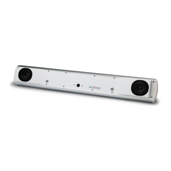
- Page 1 Atracsys LLC www.atracsys-measurement.com Route du Verney 20 Atracsys-Support@smith-nephew.com 1070 Puidoux Switzerland +41 (0)21 533 09 00 fusionTrack 500 User manual File name fTk500_InstructionsHowToUse.pdf Document type Manual Version v4.5.2 Revision 8403a38 Pages Date 17th June 2020...
-
Page 2: Table Of Contents
Contents Glossary Disclaimer of Warranties and Limitations of Liability 1 Important information 1.1 Warnings ..........1.2 Caution . - Page 3 User manual Version: v4.5.2 5.6.2 fusionTrack in a ME system ....... 28 5.6.3 Annex: Explanation of applied part .
- Page 4 13.2 Running the procedure ........78 13.3 The accuracy verification tool from Atracsys ......78 14 Electromagnetic compatibility 14.1 Essential performances .
- Page 5 19 Licences 19.1 Atracsys fusionTrack SDK headers and library ......95 19.2 Hashing code ......... . . 95 19.3 About JsonCpp .
-
Page 6: Glossary
Atracsys servers, in case a detailed report is asked for.. The fusionTrack 500 is able to externally provide different signals via its EIO port. These signais can be the exposure of the tracker; the strobe of the IR LEDs; a user trigger or the device timestamp . - Page 7 User manual Version: v4.5.2 Marker Often also called rigid body. Mechanical structure with known geometry on which several fiducials are firmly attached. As soon as the tracking system detects and reconstructs at least three fiducials, the six degrees of freedom are computed by the system. Navigation system A navigation system is composed of at least a tracking system and a computer on which an IGS software is running.
-
Page 8: Disclaimer Of Warranties And Limitations Of Liability
The user’s right to recover damages caused by fault or negligence on the part of Atracsys shall be limited to the amount paid by the user to Atracsys for provision of this doc- ument. In no event shall Atracsys be liable for special, collateral, incidental, direct, indirect or consequential damages, losses, costs, charges, claims, demands or claim for lost profits, data, fees or expenses of any nature or kind. -
Page 9: Important Information
Important information This documentation provides detailed information about the fusionTrack system. Information from this chapter should be read before continuing with the rest of the document. This document contains user information for the physical and software installation of the fusionTrack system. 1.1 Warnings In the whole documentation, warnings are indicated with this symbol and graphics. -
Page 10: Caution
Magnetic Resonance Imaging or devices generating X-Rays. If you intend to operate the fusionTrack in such environments, please contact Atracsys. The fusionTrack device is a precision instrument and has to be handled with greatest care. If it receives a shock, falls on any surface or is transported without adequate packaging, it can easily be damaged or decalibrated. -
Page 11: Device Label
User manual Version: v4.5.2 The fusionTrack device degree of protection against dust and fluids (IEC standard 60529). First digit: Solid particle protection Level 2: Protected from touch by fingers and objects greater IP20 than 12 mm. Second digit: Liquid ingress protection Level 0, Not protected from liquids. -
Page 12: Contact Information
+41 (0)21 533 09 00 1.7 Updates The latest version of this document can be downloaded from Atracsys website. The address, as well as the required username and password are provided by Atracsys, please refer to the ‘Information for user’... -
Page 13: Introduction
This document presents how to install and use the fusionTrack system. It is, as well as the current fusionTrack software, continuously improved and may differ from one version to another. For any problem, question or suggestion do not hesitate to contact Atracsys either by email or by phone (see Section 1.6). -
Page 14: Device Shelf Life
User manual Version: v4.5.2 2.2 Device shelf life The shelf life of the fusionTrack is four years based on five hours of use per working day. However, the shock sensor battery should be recharged every 6 months, see Chapter 4 for more details. 2.3 Device specifications The specifications of the fusionTrack devices (model fTk500) are presented in Table 2.1. - Page 15 User manual Version: v4.5.2 Device fusionTrack 500 Model fTk500 Dimensions (L × W × H) 520 mm × 80 mm × 95 mm Weight 2.16 kg Typical fiducial localisation error at Up to 2.0 m 0.08 mm RMS / 0.17 mm 95% CI calibration time Up to 2.4 m 0.11 mm RMS / 0.22 mm 95% CI...
-
Page 16: Description Of The Fusiontrack System
Description of the fusionTrack system The fusionTrack family of Optical Tracking Systems is a flexible, real-time tracking technology based on a stereo camera approach. The fusionTrack is based on measuring the 3D position of fiducials to provide real-time orientation and position of each marker. For shock and temperature stability, the cameras inside the fusionTrack housing are floating (see Figure 3.1) and therefore the fusionTrack is not designed to measure absolute positions (positions and rotations in respect to the fusionTrack housing / the fixation base). -
Page 17: The Fusiontrack Device
User manual Version: v4.5.2 3.2 The fusionTrack device Here below is a simple description of its operation: 1. The fusionTrack illuminators emit infrared (IR) light, like the flash of a regular camera; 2. The IR light reflects on passive markers or triggers active markers which then emit IR light; 3. -
Page 18: Power Input
User manual Version: v4.5.2 Figure 3.3: The fusionTrack backplane, showing: (7) RJ-45 connector, provides the power and the trans- mission of data between the fusionTrack and a computer; (8) Power switch, switching on and off the device (9) Surface allowed for 4× M4 screws or tripod mount; (10) Extension port connection; (11) Ethernet RX LED (see Section 3.2.3);... - Page 19 The specifications of Power Source Equipment (PSE) PoE compliant is given in Table 3.1. The list of PoE+ power supplies successfully tested by Atracsys is found in Table 3.2. The list of PoE+ power supplies with detected interoperability issues are listed in Table 3.3.
-
Page 20: Cables
Table 3.3: PoE+ devices and midspan injectors with a known interoperability issue. 3.2.2 Cables Atracsys does not supply cables with the fusionTrack system, as standard Cat 5e Ethernet cables can be used. The usage of shielded and unshielded cables are possible. In case a PoE+ power supply is used, two Ethernet cables are needed (one from the host PC to the PoE+ power supply and one from the PoE+ power supply to the fusionTrack device). - Page 21 Device is ready. Device Status LED Blue Flashing Communication with the firmware was detected. Flashing Indicates a fatal error, please contact Atracsys. Flashing Link 10BASE-T & PoE Type 2/Unknown Orange Flashing Link 100BASE-T & PoE Type 2 Ethernet RX LED...
-
Page 22: Shock Sensor
The fusionTrack device is equipped with a shock detection circuitry, hereafter called shock sensor. The shock sensor is a very low power, battery powered electronic unit designed by Atracsys based on a mi- crocontroller (µC). The unit is composed of three accelerometers, a temperature sensor, a real time clock (RTC) and a non-volatile memory. -
Page 23: Error Register
All critical failures lead to a stopped boot in the factory firmware with the status LED flashing red. The device need to be connected to the atnet64 software, and the result of the error register needs to be sent to Atracsys support team Atracsys-Support@smith-nephew.com. The shock report can be downloaded, this is explained in Section 10.5. -
Page 24: Hardware Installation
When unpacking the received fusionTrack, it must be checked that no item is missing, and no item is damaged. The invoice or shipping paper defines the list of items in the shipment. The Atracsys after sale service should be contacted in case of a missing or damaged item. -
Page 25: Least Favorable Working Conditions
User manual Version: v4.5.2 The fusionTrack products are intended for indoor use in professional healthcare facility environments like physician offices, dental offices, clinics, limited care facilities, freestanding surgical centers, freestanding birthing centers, multiple treatment facilities, hospitals (emergency rooms, patient rooms, intensive care, surgery rooms) except for: - near active HF (high frequency) SURGICAL EQUIPMENT, - inside RF (radio frequency) shielded room of an ME SYSTEM for magnetic resonance imaging, where... -
Page 26: Mounting The Fusiontrack Device
User manual Version: v4.5.2 Environmental parameter Range Temperature 10 °C to 55 °C Atmospheric pressure 50 kPa to 106 kPa Relative humidity 10 % to 90 % non-condensing Table 5.3: Recommended long-term (1 week 6 months) storage and transportation conditions. - keep away from strong heat or cold;... -
Page 27: Network Connection Of The Fusiontrack Device
The fusionTrack device can be used a Ethernet to USB adapter, however, the performances are not guaranteed. Tests performed by Atracsys show that the Ethernet to USB adapters listing in Table 5.6 allow a smooth usage of the GUI demo program. -
Page 28: The Fusiontrack
User manual Version: v4.5.2 Model Remark Lenovo ThinkPad USB 3.0 Ethernet Adapter P/N: 7 kbits Jumbo frames maximum. 4X90E51405 Table 5.6: List of tested Ethernet to USB adapters. 5.6.1 The fusionTrack Even though no patient contact is necessary for the fusionTrack in normal operation, the fusionTrack has to be considered as Type B applied part since the fusionTrack can potentially be placed within the patient environment (up to 1.5 m from the patient). -
Page 29: Fusiontrack In A Me System
User manual Version: v4.5.2 5.6.2 fusionTrack in a ME system This section is provided as information only, the integrator has to discuss and verify the fusionTrack integration with a certification body. If the fusionTrack is used as a component in a Medical Electrical system (ME system), the whole system has to respect the 60601-1 standard in order to guarantee the safety of the operator and the patient: - Requirements of the 60601-1 to provide protection against electric shock;... -
Page 30: Annex: Explanation Of Applied Part
User manual Version: v4.5.2 a medically certified separating transformer between the mains and the ME system will guarantee the total touch current to stay under the required limits. Additionally, the medically certified separating transformer also increases the means of protection regarding electric shock for the whole ME system and also for the individual components. -
Page 31: Software Installation
- Pre-compiled software examples, with the corresponding source code; - Documentation of the Application Programming Interface (API); - Some predefined marker files. The latest installers are found on Atracsys website, using the username and password provided by Atracsys. 6.1 Windows installation The installer for Windows is a wizard which allows an easy installation with possible customisation of the setup. -
Page 32: How The Fusiontrack Device Works
How the fusionTrack device works This chapter describes the fusionTrack device functioning. 7.1 Communicating with the fusionTrack device The fusionTrack communicates with the host PC via Ethernet using a proprietary protocol. The SDK shipped with the fusionTrack device implements the bidirectional communication: e.g. retrieving information from the fusionTrack device, setting options and reading the data. - Page 33 User manual Version: v4.5.2 In order to be tracked by the fusionTrack device, the markers must lie inside the working volume de- scribed in Figure 7.3. It should be noted this volume is not the same as the validated volume, shown on Figure 2.1 and Figure 2.2.
-
Page 34: Information Provided By The Fusiontrack Device
User manual Version: v4.5.2 7.3 Information provided by the fusionTrack device The fusionTrack is designed to provide accurate relative measurements, and should not be used to perform abso- lute measurement. See Chapter 3 for more information. Most of the functions of the API return a status code, which indicates different levels of warnings and errors. - Page 35 User manual Version: v4.5.2 – the indices of the left and right raw data used to reconstruct the fiducial, allowing to access the information about the used raw data; – the status of the marker, which indicates whether the fiducial lies in the accuracy measurement volume or not, unioned with the statuses of the two raw datas of which it consists;...
-
Page 36: The Fusiontrack Events
User manual Version: v4.5.2 err = ftkGetLastFrame ( lib , serialNbr , frame ); ( err == FTK_OK && frame -> imageLeftStat == QS_OK ) QImage * greyPicture ( QImage ( frame -> imageHeader .width , frame -> imageHeader .height , QImage :: Format_Indexed8 ) );... -
Page 37: Temperature Compensation
User manual Version: v4.5.2 For those reasons, a new marker reconstruction algorithm was developped. For backward compatibility reasons, the old one is still used as the default, and the new one can be enabled using a dedicated option. 7.5 Temperature compensation The internal temperature of the fusionTrack device have a non-negligible rise time, which leads to a loss of trueness in both following situations: 1. - Page 38 Version: v4.5.2 A marker shall be treated as an independent medical device. Use markers as specified by Atracsys. Other risks related to markers with reflecting fiducials may occur depending on the technology used by the manufacturer, these risks cannot be treated by Atracsys.
-
Page 39: Passive Markers
User manual Version: v4.5.2 Markers or fiducials geometrically deformed due to shocks or manufacturing defects can create wrong measurements leading to patient injury. Instructions about not using ge- ometrically deformed markers or fiducials must be clearly specified in the end user manual. Markers or fiducials too close from lenses might lead to wrong measurement (see Table 2.1). -
Page 40: Active Markers
User manual Version: v4.5.2 For single-use markers, the end user manual must clearly state that the markers should not be reprocessed. The markers packaging must be marked with a label indicating they cannot be reprocessed. For single-use fiducials, instructions about replacing new fiducials after every (single) use must be clearly specified by the integrator in the end user manual. - Page 41 User manual Version: v4.5.2 Active markers with batteries shall be handle with care. Op- erator who gets in contact with battery leakage incurs a risk of chemical burn. The integrator has to indicate in the end user manual that the battery of an active marker has to be removed after usage, especially in the case the active marker undergoes a sterilisation procedure.
-
Page 42: Marker Geometry Files
User manual Version: v4.5.2 Markers have to meet the IEC60601-1 requirement regard- ing ‘Protection against excessive temperatures and other hazards’. The integrator should use redundant fiducials (i.e. four or more fiducials instead of only three) and require the recon- structed marker to use all of them. The battery must be removed from the marker after use, in order to prevent damage to the marker which may be caused by battery leakage. -
Page 43: Marker Tracking Parameters
User manual Version: v4.5.2 [fiducial1] x=-11.811 y=500.934 z=0.048 [fiducial2] x=-11.77 y=970.879 z=0.266 [fiducial3] x=-11.759 y=1165.952 z=-0.131 Listing 7.2: Example of geometry file 7.8 Marker tracking parameters The tracking of markers (and fiducials) is tuned by a small set of parameters: - epipolar max distance;... -
Page 44: Phantom Fiducials
User manual Version: v4.5.2 Registration mean error The registration mean error sets a tolerance on the error returned by the marker registration algorithm. The computed error is a measurement of the deformation between the re- constructed marker and the theoretical geometry, linked to the accuracy of the positioning of the marker. The bigger the registration error, the looser the requirement on the system accuracy. -
Page 45: Stray Fiducials
User manual Version: v4.5.2 7.10 Stray fiducials A stray fiducial is a fiducial which was not used to reconstruct a marker. The SDK allows to get the 3D position of such fiducials. The stray fiducials may include phantom fiducials (see definition in Section 7.9), and the application must take care of removing them, and checking the validity of the reported positions. -
Page 46: Using The Fusiontrack System
The fusionTrack device must be cleaned as described in Chapter 17. The Atracsys SDK is shipped with precompiled softwares. From the install directory they can be found in the relative path fusionTrack SDK/bin . Their use is described in the following two sections. Each soft- ware can take at least an additional configuration file as argument, using the -c/--config path_to_file. -
Page 47: Library Related Options
User manual Version: v4.5.2 4. 3D reconstruction related options (e.g. epipolar tolerance); 5. Wireless related options (e.g. marker button status streaming). float or ftkBuffer), a read / write status and an optional ‘global’ flag Each option has a type (int32, indicating whether the option is global, in which case it is handled at the library level and must be accessed by specifying 0uLL as serial number. - Page 48 User manual Version: v4.5.2 Name Type Description int32, Image Compression Allows to access the picture compression thresh- Threshold read / write, old, i.e. minimum pixel intensity for a pixel to permanent be considered white. Increasing the value de- creases the compressed picture size. int32, Image Integration Time Allows to access the sensor integration time, i.e.
- Page 49 User manual Version: v4.5.2 Name Type Description int32, Data sending Allows to toggle on/off the data sending by the read / write fusionTrack device. int32, Enables lasers Allows to switch on/off the two pointing lasers of read / write, the fusionTrack device. A value of 0 disables both permanent lasers, 1 enables the left laser, 2 enables the right laser whilst 3 enables both of them.
- Page 50 User manual Version: v4.5.2 Name Type Description ftkBuffer, Load environment This option allows to restore the value of all read- /write options from a JSON file. The ftkBuffer write-only contains the path to the JSON file to load (see Section 8.1.6). int32, MTU size Allows to read the MTU size used by the...
-
Page 51: Detection Stage Related Options
User manual Version: v4.5.2 8.1.3 Detection stage related options This section presents the options which are related to the 3D reconstruction of points and markers. Name Type Description float32, Blob Minimum Aspect Defines the the minimal aspect ratio to consider Ratio read / write a raw data during the raw detection phase. -
Page 52: Wireless Related Options
User manual Version: v4.5.2 Name Type Description int32, Tracking time span Defines how many frames in the past the algo- read / write rithm will inspect in order to identify a raw data associated to a marker. int32, New marker reco algo- Toggles between the old marker reconstruction rithm read / write... -
Page 53: Environment And Options
SDK version used for generation. This allows to ensure the saved data are correctly applied when loaded. 8.2 User interface software ‘demo.exe’ The Atracsys SDK (documented in [1]) is shipped with a precompiled (GUI) program. This program is run by executing demo64.exe. This program consists of a main window, which is composed of several panels, and a secondary window showing a 3D representation of the scene (Windows only). - Page 54 Figure 8.1: Running GUI program. - ‘Geometry → Geometry X’ (un)loads geometry with ID X. Unless specified differently during in- stallation, geometry files are located at C:\Program Files\Atracsys\[sTk ]Passive Tracking SDK\data and user-defined geometries are loaded from %APPDATA%\Atracsys\PassiveTrackingSDK A greyed-out file indicates the file could be seen but not read (due to a syntax error for instance).
- Page 55 User manual Version: v4.5.2 3. the coordinate of the cursor in the picture space 4. the value of the hovered pixel 5. the stability of the acquisition frequency and the device internal temperatures (when unstable the square is orange, blue is used for stable values). Right panel On the right-hand side of the window is a dockable panel, allowing to change the values of the available options, perform marker recalibration, and export data.
- Page 56 User manual Version: v4.5.2 - Paired markers contains a table (See Figure 8.2) where paired markers are listed. The statuses of the buttons of the paired markers as well as the battery state are displayed. When a field is in RED, it means that the value has not been updated recently (2 second for the battery, 50ms for the buttons).
- Page 57 User manual Version: v4.5.2 Figure 8.2: The Paired markers widget lists all the paired wireless markers and display their statuses. - Registration Mean Error; - Matching Maximum Missing Points; - Tracking range; - Tracking time span. The Display-related option tab gathers options which are specific to the GUI, i.e. they do not correspond to any option from the SDK.
-
Page 58: Recalibration Of A Marker
The old geometry is automatically disabled and the new one enabled. The produced file is stored in a user-specific location (%APPDATA%\Atracsys\PassiveTrackingSDK on Windows). The recalibration algorithm can reassign fiducial IDs, i.e. fiducial 0 from the old geometry might become fiducial 2 in the new one. -
Page 59: Dumping The Data
8.3 Command line software samples The Atracsys SDK is also shipped with precompiled command line softwares, which show C++ code ex- amples of how to use the SDK. From the install directory they can be found in the relative path fusionTrack SDK/bin . - Page 60 The temperature sensors are identified by a number, and Atracsys guarantees that a sensor with a given ID will always be located at the same place, and that there always will be at least one sensor in each of the following regions: - the left part of the device;...
- Page 61 User manual Version: v4.5.2 Figure 8.4: Temperature sensors location, top view. Figure 8.5: Temperature sensors location, isometric view.
- Page 62 4. the data taking must be enabled. ftk18_DumpDeviceInfo shows how to get a dump of the device information. In case of a problem, this dump can be sent to Atracsys for diagnostics. The software creates an XML file, which contains the following information (non-exhaustive list): - date and time;...
-
Page 63: Latency Measuring
This is the reason why the ‘Picture rejection threshold’ option has been introduced in the 3.0.1 version of the SDK. Atracsys now provides a sample which allows to tune the value of the ‘Picture rejection threshold’ option according to the target environment and running platform: ftk20_Latency, available both as a pre-compiled binary and source code. -
Page 64: Compilation Of Provided Samples
The SDK comes with helper cmake files, which allows to simply use either the C or the C++ sdk with minimal efforts in a custom-made CMakeListst.txt file, as demonstrated in Listing 8.5. set(Atracsys_DIR "path_to_your_install") find_package(Atracsys REQUIRED COMPONENTS SDK AdvancedAPI) # Using the C API add_executable(test_sample_c test_sample.cpp) target_link_libraries(test_sample_c Atracsys::SDK) -
Page 65: Windows Compilation
-G " Visual Studio 15 2017 Win64" "C:\ Program Files\ Atracsys \ fusionTrack SDK\ samples " cmake -G " Visual Studio 16 2019" -A x64 "C:\ Program Files\ Atracsys \ fusionTrack SDK\ samples " 3. Open the samples.sln solution and compile. -
Page 66: Language Bindings
Language bindings In this chapter are described the different bindings Atracsys makes available to the users. The reference implementation is the distributed C / C++ API. The other language bindings are not subject to torough test- ing, as the C / C++ do. - Page 67 In order to compile the wrapper on Windows, the cmake generation must be set in 64 bits (See List- ing 9.1) REM In a temporary folder do: cmake -DCMAKE_GENERATOR_PLATFORM =x64 "C:\ Program Files\ Atracsys \ fusionTrack SDK x64\ matlab " cmake --build . Listing 9.1: Compiling the Matlab wrapper.
-
Page 68: Command Line Utility Tool
Chapter 6. The procedure is the following: 1. Launch the atnet (usually located in the INSTALL_PATH/bin folder on Linux and in C:\Program Files\Atracsys\fusionTrack SDK x64\bin on Windows) with the 0 argument; $INSTALL_PATH /bin % ./ atnet64 .exe 0 2. (Re)boot the fusionTrack;... -
Page 69: Updating The Firmware Of The Fusiontrack Shock Detection Unit
User manual Version: v4.5.2 Figure 10.1: Example of an atnet session to upgrade the application firmware. 10.3 Updating the firmware of the fusionTrack shock detection unit When performing step 7, the fusionTrack must be at room temperature, and switched off for at least 4 h. The update of the fusionTrack shock detection unit firmware is performed through the command line software atnet. -
Page 70: Updating The Firmware Of The Wireless Markers Using The Fusiontrack
User manual Version: v4.5.2 Figure 10.2: Example of updating the shock sensor detection unit firmware. 10.4 Updating the firmware of the wireless markers using the fusionTrack The update of the wireless active markers with a fusionTrack is done through the command line software atnet. -
Page 71: Obtaining A Shock Report
Section 10.1. The process is in two steps: 1. The data is downloaded from the device; 2. The data is sent to Atracsys’ processing server and the pdf report is sent by email. The procedure is the following: 1. -
Page 72: Control The Operability Of The Fusiontrack System And Instruments
Control the operability of the fusionTrack sys- tem and instruments In this chapter is explained how to guaranty the operability of the fusionTrack. Outputs and alert mes- sages are generated to help protect against hazardous behaviours. They can also be used to validate the fusionTrack operability. -
Page 73: Control Marker Registration And Epipolar Errors
User manual Version: v4.5.2 11.2 Control marker registration and epipolar errors At any time, the marker registration error and the marker epipolar error (defined in Section 7.8) computed by the SDK must be monitored. The integrator must define thresholds above which the errors can lead to unacceptable risk for the patient. -
Page 74: Control Optical Elements And Ir Illumination
User manual Version: v4.5.2 A too high temperature due to internal overheat, or due to the fusionTrack device being wrongly placed near a heat source, might lead to unexpected temperature measurements. The integrator has to trigger an error message indicating that the fusionTrack sensor has detected an abnormal temperature within the system. -
Page 75: Integrator Software
User manual Version: v4.5.2 11.6 Integrator software At any time, the hardware (i.e. the fusionTrack device), the firmware and the software (i.e. the SDK) must be compati- ble. A software dysfunction due to software crash might cause wrong measurements causing patient injury. The integrator has to indicate in the end user manual that the fusionTrack device must be restarted when the software freezes or crashes. - Page 76 User manual Version: v4.5.2 A software dysfunction due to unavailable data could lead to wrong measurements or the non performing of the surgery as planned. The integrator has to perform unit tests accord- ing to the end application of the fusionTrack device. A non respect of the software functionality or unexpected software failure might cause wrong measurements.
-
Page 77: The Zeroing Method
The zeroing method This method must be implemented by the integrator and be automatically run at the application startup and inform the user on how to proceed. The zeroing method is a procedure which checks that the fusionTrack device and the used markers are correctly calibrated. -
Page 78: Running The Procedure
User manual Version: v4.5.2 Figure 12.2: Running the zeroing procedure. - a deformed pointer or marker; - a decalibrated fusionTrack device; - dirty optics on the fusionTrack device. 12.2 Running the procedure The zeroing procedure must be integrated in the workflow at each startup of the application or as soon as the pointer (whole pointer or any of its fiducials in case of passive markers) is changed. -
Page 79: The Accuracy Verification Tool (Avt)
5 surgeries, whatever comes first. 13.3 The accuracy verification tool from Atracsys Atracsys offers as an aditional accessory a rigid body designed to perform accuracy verification on the fusionTrack. Along with this rigid body, Atracsys provides the required software to perform the capture of data and the accuracy analysis. -
Page 80: Electromagnetic Compatibility
Electromagnetic compatibility The fusionTrack is medical electrical equipment and needs special precautions regarding EMC and needs to be installed and put into service according to EMC information provided in this document. EMC tests have not included any AC-adapter with the product. Applied standards EN 60601-1-2:2007 +AC:2010 Medical electrical equipment –... - Page 81 User manual Version: v4.5.2 Use of accessories, transducers and cables other than those specified or provided by Atracsys could result in increased electromagnetic emissions or decreased electromagnetic immunity of this equipment and result in improper operation and/or loss of performance. Such failure can lead to wrong measurements, serious injury including death.
-
Page 82: Essential Performances
30 cm (12 inches) to any part of the fusionTrack, including cables specified by Atracsys. Otherwise, degradation of the performance of this equipment could result, which can lead to wrong measure- ments, serious injury including death. -
Page 83: Measurement Rate
User manual Version: v4.5.2 Evaluation parameter Value Blob number Constant Number of fiducials used to build a marker Constant Marker registration error Constant Registration error max - min Constant Fiducial interdistance Constant Fiducial interdistance max - min Constant With presence of a jitter, which depends on: fiducial type (LED, sphere, sticker), marker geometry, working distance. -
Page 84: Cables
User manual Version: v4.5.2 14.2 Cables Access Length Type Screened Ethernet RJ-45 port max. 100 m Cat 5e or better (un)shielded 100/1000 Mbps PoE+ Total length, i.e. before and after a potential PoE+ injector. Not intended to connect directly to outdoor cables. -
Page 85: Communication Parameters
Communication parameters The fusionTrack device uses by default the 172.17.1.7 IPv4 address, and the local UDP port is automatically chosen. These two parameters can be changed. 15.1 Changing the IP The IPv4 address of the device can be changed to fit the user’s desiderata. To change this address, the atnet software must be used. -
Page 86: Changing The Local Udp Port
User manual Version: v4.5.2 Listing 15.1: JSON file setting the IP to 172.16.2.4 Please note the UDP port used by the fusionTrack (the 3509 value) cannot currently be changed. 15.2 Changing the local UDP port The local UDP port (i.e. the random port on the machine used to communicate with the UDP server on the fusionTrack device) can be forced to a value. - Page 87 User manual Version: v4.5.2 "port ": 3509 Listing 15.3: Example of configuration allowing the connection to 2 fusionTracks.
-
Page 88: The Fusiontrack Device Authentication
A key is programmed in the fusionTrack device and in the end-user application by the integrator. The Atracsys SDK let the integrator send ‘challenges’ to the tracker whenever the need arise. For example, this can be done at startup and during surgical workflow transitions. -
Page 89: Checking The Fusiontrack Device
16.3 Checking the fusionTrack device The Atracsys SDK allows to check if the connected fusionTrack device is correctly configured. The key and challenge setting and the result getting are handled via options (see Section 8.1). The key must first be set in the SDK using the ‘Set cypher key’... - Page 90 User manual Version: v4.5.2 buffer .data[ 0xfu ] = 0x21; buffer .size = 16u; ( ftkSetData ( lib , sn , setKeyId , & buffer ) != ftkError :: FTK_OK ) // handle error std :: default_random_engine generator ; std :: uniform_int_distribution <uint64_t > distribution (); buffer .reset ();...
- Page 91 User manual Version: v4.5.2 Figure 16.1: The Authentication tab in the GUI demo allows to check a key by requesting a challenge to the connected fusionTrack...
-
Page 92: Maintenance
Maintenance In this chapter are found the instructions for maintaining basic safety and performances for the expected service life, in particular it is explained how to clean the fusionTrack device and its accessories. 17.1 Cleaning the fusionTrack device The end user manual instruction shall provide a validated cleaning and disinfection method to the end-user. -
Page 93: Effects Of Multiple Cleanings
Chapter 13. In the case of a device not passing the test, it should not be used anymore and sent back to Atracsys for repair. 17.4 Disposal of equipment To ensure environmentally responsible disposal decommissioned equipment, please contact Atracsys, see Section 1.6. -
Page 94: Troubleshooting
- Check the fusionTrack device IP address is the expected one (see Chapter 15) The fusionTrack device is beeping Contact Atracsys (see Section 1.6). and the status LED is blinking in red. 18.1.1 Wrong or damaged cables Poorer performances (degraded effective acquisition rate) are common if using 100BASE-T cables instead of 1000BASE-T ones. -
Page 95: Ftk_War_Shock_Sensor_Offline Warning
In order to clear this warning, an accuracy verification must be performed (See Chapter 13). It can be done either on site using the Atracsys accuracy verification tool or the device can be sent back to Atracsys (See Section 1.6). If done on site, the AVT user manual describes the procedure. -
Page 96: Licences
19.1 Atracsys fusionTrack SDK headers and library These files are part of the Atracsys fusionTrack library. You can freely use this SDK for your own applications. A license to use binary files of this distribution is granted to owner of infiniTrack, spryTrack and/or fusionTrack devices. -
Page 97: About Qt
User manual Version: v4.5.2 In jurisdictions which do not recognize Public Domain property (e.g. Germany as of 2010), this software is Copyright (c) 2007-2010 by Baptiste Lepilleur and The JsonCpp Authors, and is released under the terms of the MIT License (see below). In jurisdictions which recognize Public Domain property, the user of this software may choose to accept it either as 1) Public Domain, 2) under the conditions of the MIT License (see below), or 3) under the terms of dual Public Domain/MIT License conditions described here, as they choose. -
Page 98: About Freeglut
User manual Version: v4.5.2 Qt licensed under the GNU LGPL version2.1 is appropriate for the develpment of Qt applications (proprietary or open source) provided you can comply with the terms and conditions of the GNU LGPL version 2.1. Qt licensed under the GNU General Public Licences version 3.0 is appropriate for the develpment of Qt applications where you whish to use such applications in combination with software subject to the terms of the GNU GPL version 3.0 or where you are otherwise willing to comply with the terms of the GNU GPL version 3.0. -
Page 99: About Fltk
User manual Version: v4.5.2 19.8 About FLTK The AVT software is based in part on the work of the FLTK project (http://www.fltk.org) version 1.3.3. December 11, 2001 The FLTK library and included programs are provided under the terms of the GNU Library General Public License (LGPL) Version 2, June 1991 with the following exceptions: 1. -
Page 100: A Mathematical Considerations
· T A.2 Marker pose Atracsys gives access to the marker orientation, either via the ftkMarker::rotation or the atracsys:: MarkerData::_Rotation fields. The ftkMarker::rotation matrix is stored such that it is accessed like this: ftkMarker::rotation[rowId][columnId], and the information is simply copied into the atracsys ::MarkerData::_Rotation field (i.e. -
Page 101: Inverting A Marker Pose
= framePtr -> markers [ 0u ]. rotation [ 1u ][ 2u ]; // this is -0.0828 // C++ API example : frame is a atracsys :: FrameData instance r21 = frame. markers (). front (). rotation ().at( 2u ).at( 1u );... -
Page 102: B Warning Summary
Warning summary This chapter gathers all warnings spread in the current document, so that it can be used as a checklist. In the whole documentation, warnings are indicated with this symbol and graphics. The information from the accompany- ing paragraph must be followed to avoid patient or operator injury. - Page 103 Magnetic Resonance Imaging or devices generating X-Rays. If you intend to operate the fusionTrack in such environments, please contact Atracsys. The fusionTrack device is a precision instrument and has to be handled with greatest care. If it receives a shock, falls on any surface or is transported without adequate packaging, it can easily be damaged or decalibrated.
- Page 104 User manual Version: v4.5.2 The fusionTrack must not be used if a hot hair outlet is present between the fusionTrack and the markers. The re- fraction index changes of the hot and cold air interfaces could cause wrong measurements. The fusionTrack has to be placed horizontal. An orientation other than horizontal (e.g.
- Page 105 Version: v4.5.2 A marker shall be treated as an independent medical device. Use markers as specified by Atracsys. Other risks related to markers with reflecting fiducials may occur depending on the technology used by the manufacturer, these risks cannot be treated by Atracsys.
- Page 106 User manual Version: v4.5.2 Markers or fiducials geometrically deformed due to shocks or manufacturing defects can create wrong measurements leading to patient injury. Instructions about not using ge- ometrically deformed markers or fiducials must be clearly specified in the end user manual. Markers or fiducials too close from lenses might lead to wrong measurement (see Table 2.1).
- Page 107 User manual Version: v4.5.2 Active marker electronics has to be completely sealed in or- der to avoid liquid penetration due to cleaning. The inte- grator has to indicate in the end user manual instructions to clean active markers. The integrator has to specify in the end user manual that the operability verification procedure (see Chapter 12) must be done after each cleaning.
- Page 108 User manual Version: v4.5.2 An active fiducial marker is able to transmit its individual parameters and data to the system. It can also notify the fusionTrack with alert messages. An error message alert- ing that battery power is low is sent. That message must be handled by the integrator to alert the operator that the marker is not considered as operational due to a low battery and the fiducials must be turned off.
- Page 109 User manual Version: v4.5.2 At any time, the marker registration error and the marker epipolar error (defined in Section 7.8) computed by the SDK must be monitored. The integrator must define thresholds above which the errors can lead to unacceptable risk for the patient.
- Page 110 User manual Version: v4.5.2 Any degradation of optical elements due to the cleaning method or scratches during transport can lead to wrong measurements. Optical elements should be handled with care during transport and storage. The integrator has to mention in the end user manual the cleaning methods for optical elements as described in Chapter 17.
- Page 111 User manual Version: v4.5.2 In the case of the fusionTrack device stops functioning dur- ing use / operation, it is the integrator responsibility to en- sure that surgeon resume operation with the conventional method. Any wrong settings of the fusionTrack device, misuse of the SDK or misuse of the OS functionalities might cause wrong measurements causing patient injury.
- Page 112 Use of accessories, transducers and cables other than those specified or provided by Atracsys could result in increased electromagnetic emissions or decreased electromagnetic immunity of this equipment and result in improper operation and/or loss of performance.
- Page 113 User manual Version: v4.5.2 The end user manual instruction shall provide a validated cleaning and disinfection method to the end-user. The integrator must ensure markers are not deformed after sterilisation.
-
Page 114: References
References [1] Atracsys LLC, Atracsys Passive SDK API documentation (doxygen documentation). [2] http://en.wikipedia.org/wiki/INI_file, 2014. Online; accessed 2015-01-13. [3] Roger M. Needham, David J. Wheeler, “Tea extension,” tech. rep., Computer Laboratory, University of Cambridge, 1997. [4] A. F. Möbius, Der barycentrische Calcül: ein neues Hilfsmittel zur analytischen Behandlung der Geome-...
Need help?
Do you have a question about the fusionTrack 500 and is the answer not in the manual?
Questions and answers